Piping structure having leak detection function and leak detector

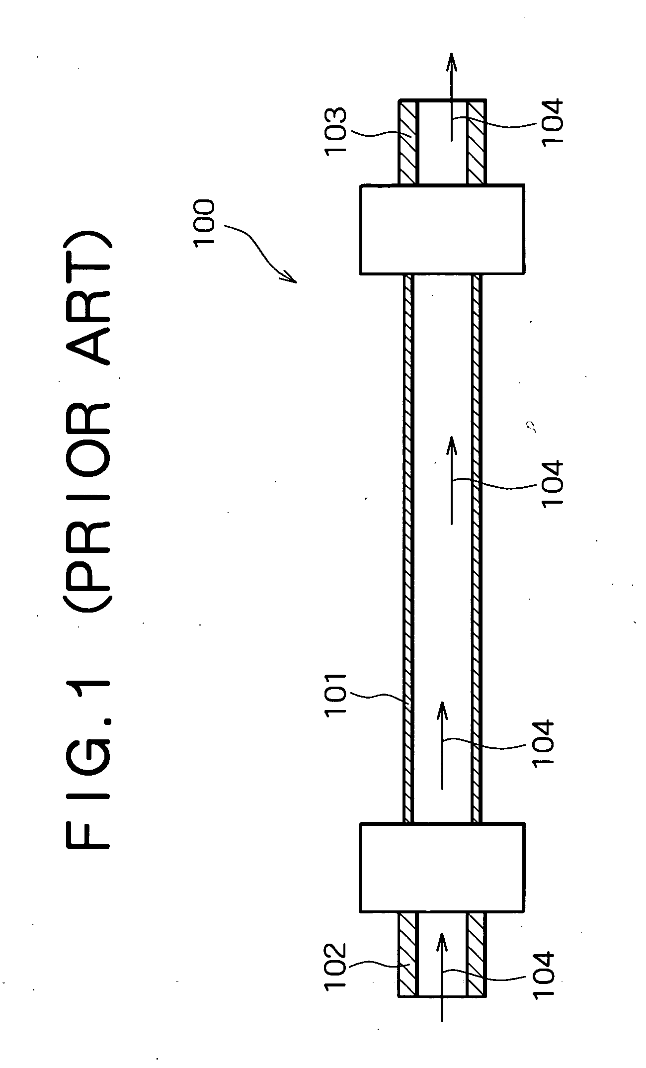
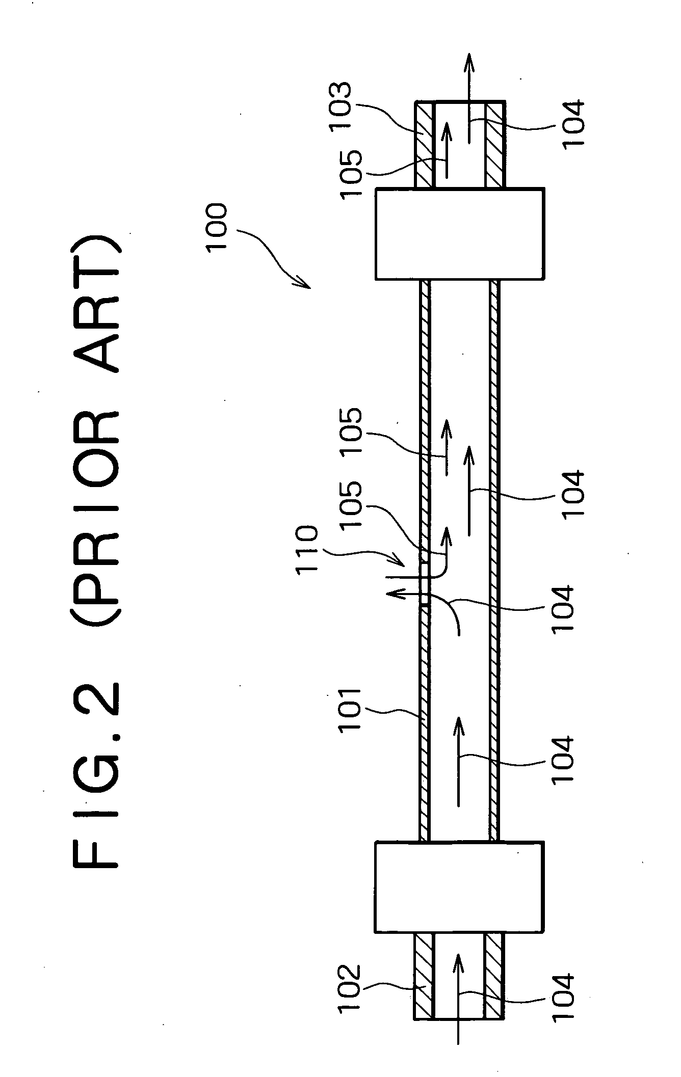
a technology of leak detection and pipe structure, which is applied in the direction of fluid tightness measurement, instruments, pipe couplings, etc., can solve the problems of time-consuming and laborious various investigations, the conventional piping structure b>100/b> cannot detect the leakage of gas flowing through, and the effect of minimizing the effect of produ

Inactive Publication Date: 2005-08-04
LASERFRONT TECH
View PDF7 Cites 49 Cited by
  • Summary
  • Abstract
  • Description
  • Claims
  • Application Information

AI Technical Summary

Benefits of technology

[0024] According to the present invention, since the covering member encloses the pipe and the pressure measuring device measures the variation of the pressure in the hermetic space formed between the covering member and the pipe, the occurrence of a breakage in the pipe can be detected. Further, since the same gas or liquid as the one flowing through the pipe is sealed in the hermetic space, even if a breakage occurs in the pipe, there is no risk that the gas or liquid flowing through the pipe is mixed with the impurity, thereby minimizing the effect on the product.

Problems solved by technology

The conventional piping structure 100, however, cannot detect the leakage of the gas flowing therethrough.
Therefore, a problem with using the conventional piping structure 100 is that time-consuming various investigations will be required until it is found out that the process in the CVD equipment deteriorates due to the occurrence of a leakage.
Another problem is that, even if it is recognized that a leakage occurs, it takes long time to specify the origin of the leakage or the breakage 110.
The conventional methods described above, however, have the following problem.
The conventional methods, however, cannot solve this problem.

Method used


Image

  • Piping structure having leak detection function and leak detector
  • Piping structure having leak detection function and leak detector
  • Piping structure having leak detection function and leak detector

Examples


Embodiment Construction

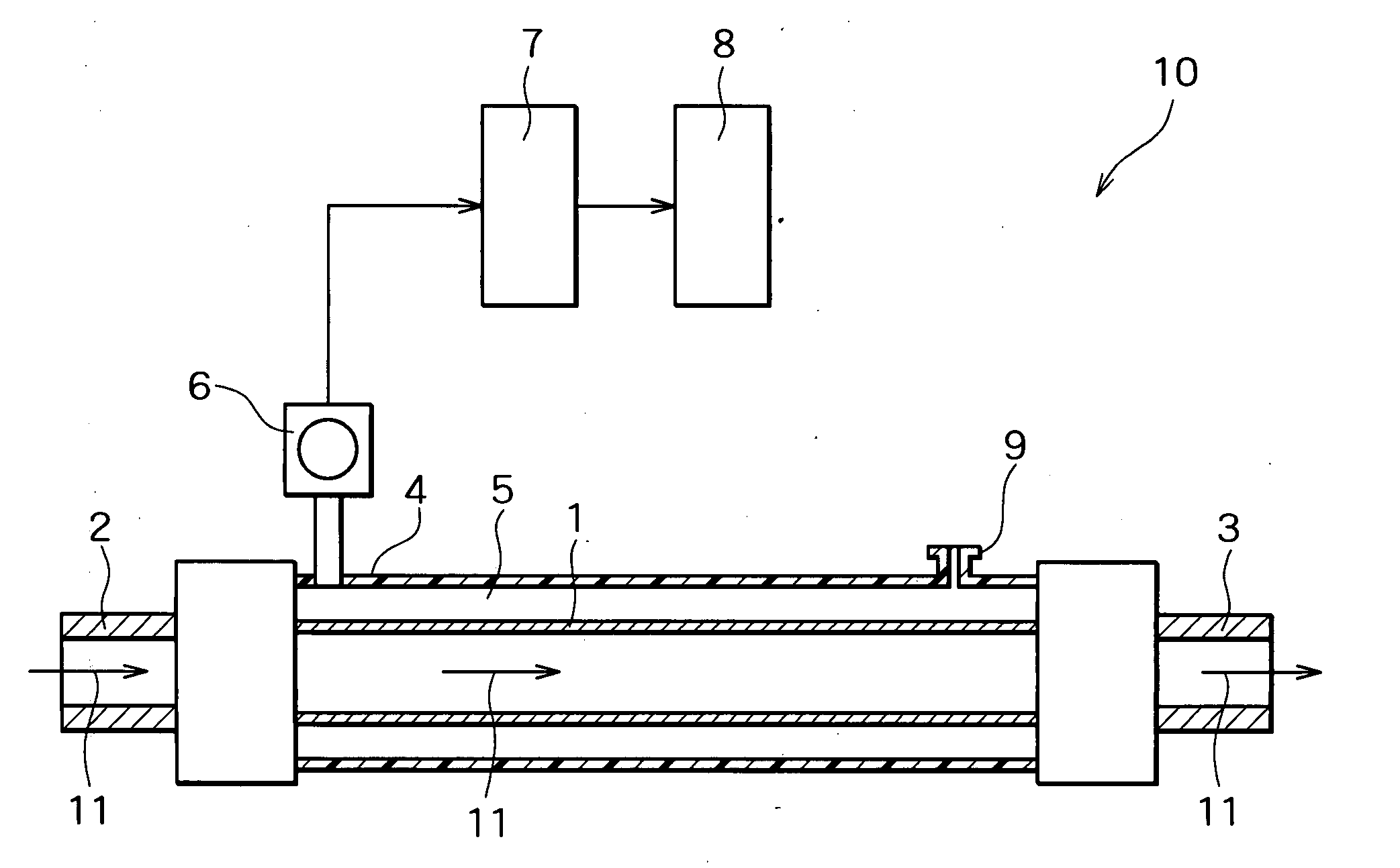
[0029] A piping structure having leak detection function according to an embodiment of the present invention will now be described with reference to the attached drawings. FIG. 3 is a cross-sectional side view illustrating a piping structure of the present embodiment. FIG. 4 is a cross-sectional side view illustrating a state when a breakage occurs in the piping structure 10 shown in FIG. 3. As shown in FIG. 3, in the piping structure 10 of the present embodiment, a covering member 4 is provided so as to enclose a flexible hose 1 that allows a gas or liquid to flow therethrough, with a given space between the covering member 4 and the outer surface of the flexible hose 1. That is, the piping structure 10 has a double pipe structure comprising the flexible hose 1 and covering member 4. Gas supply pipe fittings 2 and 3, such as metal gasket face seal fittings or the like, are also attached to respective ends of the double pipe, so that a hermetic space 5 is formed by the flexible hose...


PUM


Abstract

A covering member having a valve encloses a flexible hose to form a double pipe. Gas supply pipe fittings are attached to respective ends of the double pipe to form a hermetic space between the flexible hose and covering member. The covering member also has a pressure-measuring device to which a decision unit equipped with an alarm device is connected. The same gas or liquid as the one flowing through the flexible hose is introduced to the hermetic space from the valve provided in the covering member, and sealed in the hermetic space by closing the valve. The pressure in the hermetic space is set so as to be higher than the pressure produced in the flexible hose when the gas or liquid is flowing. The pressure-measuring device measures the pressure in the hermetic space while the gas or liquid flows in the flexible hose, and the decision unit compares the measured value with a reference value. As a result, if the value measured by the pressure-measuring device is lower than the reference value, the decision unit decides that a breakage has occurred and then the alarm device activates an alarm.

Description

BACKGROUND OF THE INVENTION [0001] 1. Field of the Invention [0002] The present invention relates to a piping structure having leak detection function that allows gas or liquid to flow therethrough, and to a leak detector attached to this piping structure, more particularly to a piping structure having leak detection function and a leak detector that are preferably used in equipment for manufacturing precision devices such as semiconductor devices, liquid crystal display devices, and other devices. [0003] 2. Description of the Related Art [0004] Generally, a piping structure using a stainless steel flexible hose is connected to chemical vapor deposition (CVD) equipment used for manufacturing precision devices, such as semiconductor devices, liquid crystal display devices, and other devices, to supply a gas such as argon or the like into the chamber. FIG. 1 is a cross-sectional side view illustrating a conventional piping structure. FIG. 2 is a cross-sectional side view illustrating ...

Claims


Application Information

Patent Timeline
Patent Type & Authority Applications(United States)
IPC IPC(8): F17D5/04G01M3/08G01M3/04G01M3/26G01M3/28
CPCG01M3/283F16L2201/30F16L9/18G01M3/26
Inventor TSUKAGOSHI, MASAYUKI
Owner LASERFRONT TECH
Why Eureka
Try Eureka