Process of machining scroll member by using non-rotary cutting tool

a cutting tool and scroll member technology, applied in the direction of shaping cutters, manufacturing tools, cutting inserts, etc., can solve the problems of inability to obtain a sufficiently high degree of machining accuracy, inability to machining the holder, and inability to etc., to facilitate the machining of the workpiece, reduce the degree of fluid tightness, and improve the effect of machining accuracy

Active Publication Date: 2005-08-04
PANASONIC CORP +1
View PDF11 Cites 2 Cited by
  • Summary
  • Abstract
  • Description
  • Claims
  • Application Information

AI Technical Summary

Benefits of technology

[0024] In the non-rotary cutting tool defined in the fifth aspect of the invention, a chamfer or radius on at least one of the side cutting edge portion and the end cutting edge portion of the cutting edge is not larger than 0.03 mm. Such a sharp cutting edge facilitates machining of the workpiece with a sufficiently high degree of accuracy in the finishing step of the machining process.
[0025] In the non-rotary cutting tool defined in the sixth aspect of the invention, the side cutting edge portion of the cutting edge has the high degree of parallelism with respect to the axis of the cylindrical shank portion such that the error in the parallelism is not larger than 3 μm, while the end cutting edge portion of the cutting edge has the high degree of perpendicularity with r

Problems solved by technology

In the conventional machining process, however, each end mill attached to a spindle of a machine tool through a holder tends to suffer from its “run out” while being rotated with the spindle.
In a finishing step of a machining process, the run out of the end mill makes it impossible to obtain a sufficiently high degree of machining accuracy, which is required in machining of scroll walls of a scroll compressor, for assuring a sufficiently high degree of fluid tightness between the scroll walls and a s

Method used


Image

  • Process of machining scroll member by using non-rotary cutting tool
  • Process of machining scroll member by using non-rotary cutting tool
  • Process of machining scroll member by using non-rotary cutting tool

Examples


Embodiment Construction

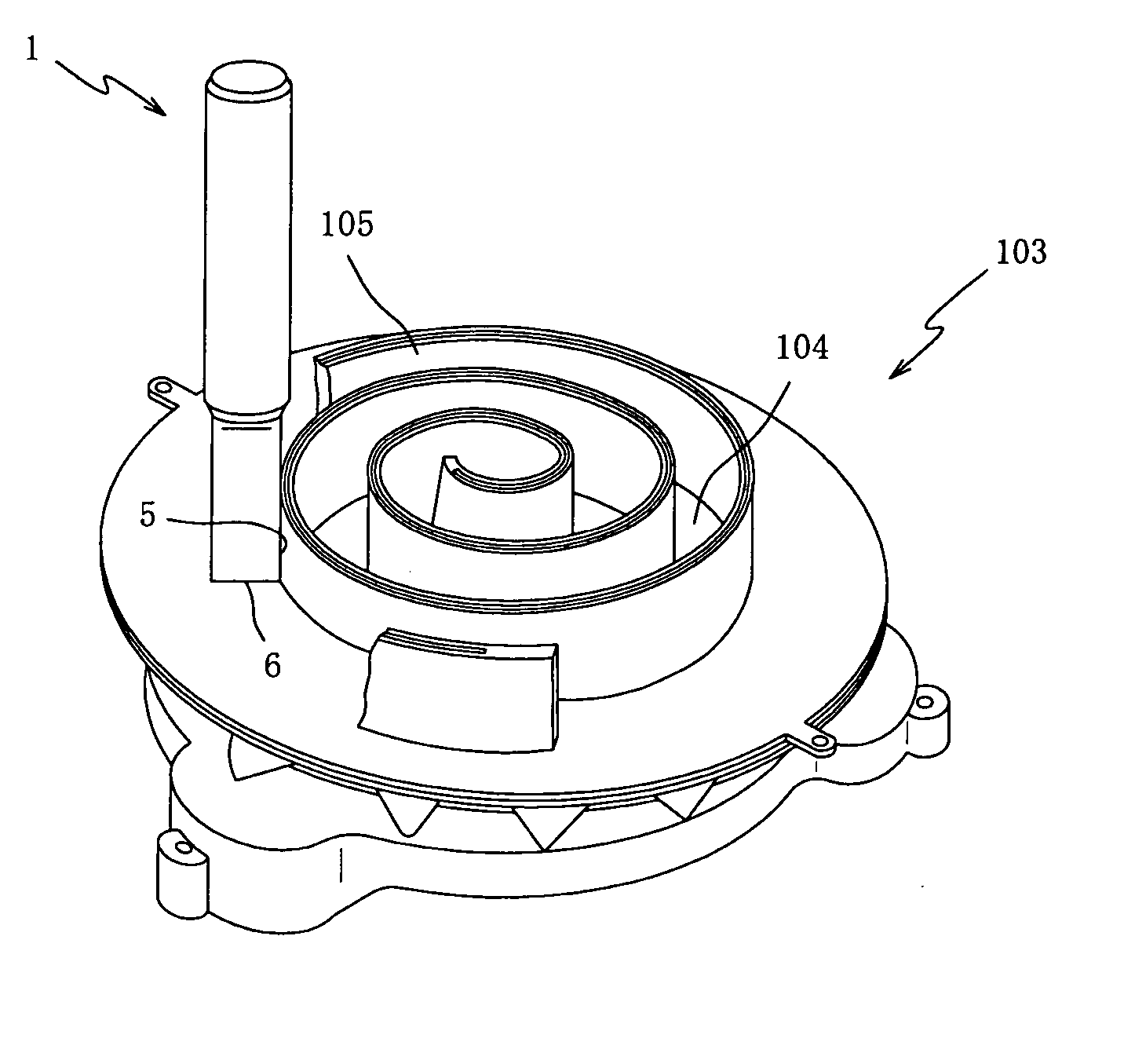
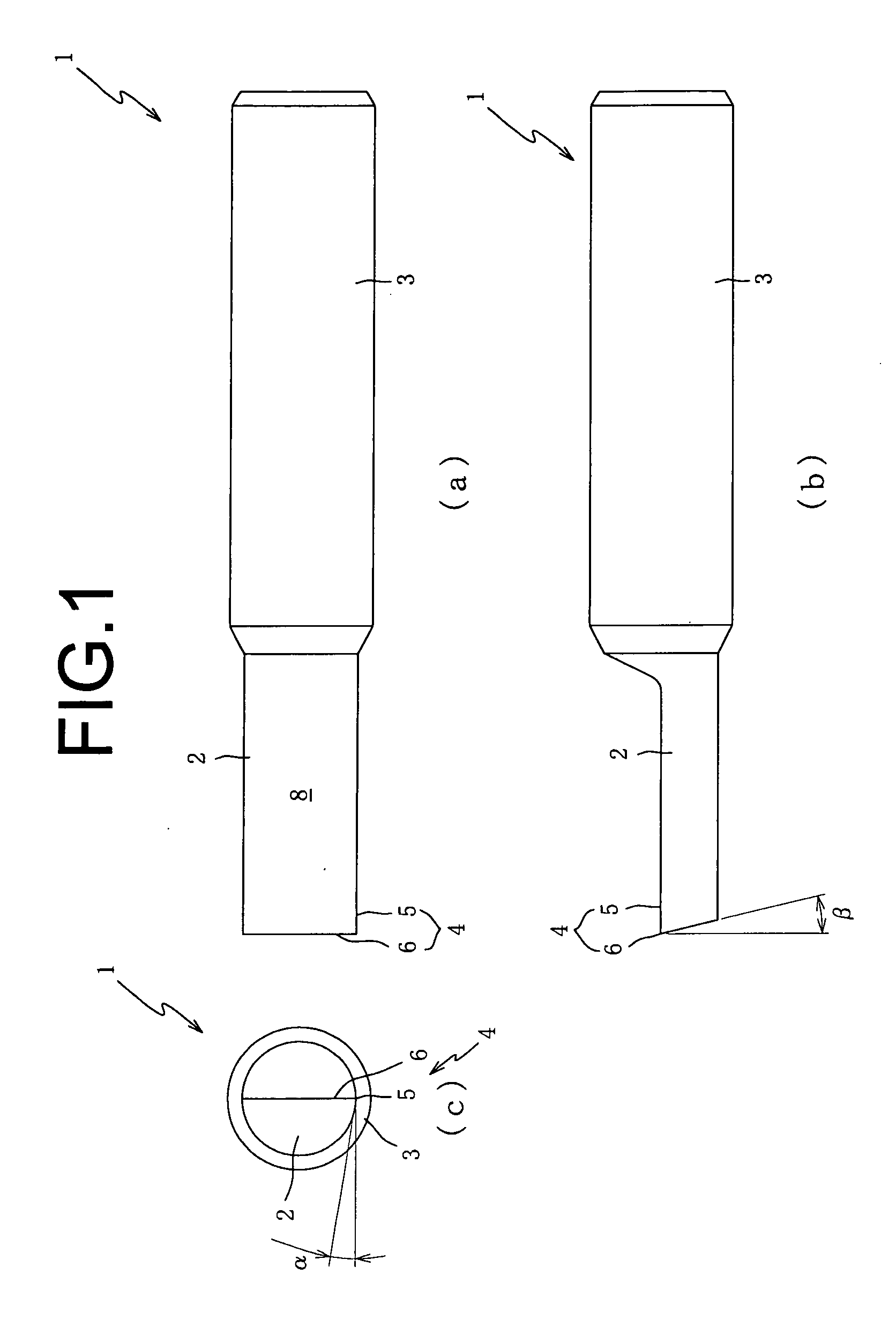
[0036] Referring first to FIG. 1, there will be described a non-rotary cutting tool 1 which is constructed according to a first embodiment of the invention. FIG. 1 is a set of three views of the non-rotary cutting tool 1, wherein its front view, side view and bottom view are given at (a), (b) and (c), respectively. The non-rotary cutting tool 1 is a so-called “gooseneck tool”, and is to be held at its end portion (right end portion as seen at (a), (b) of FIG. 1) by a suitable tool holder (not shown) so that the cutting tool 1 is fixed to a spindle of a machine tool (not shown) such as a machining center through the suitable tool holder. This non-rotary cutting tool 1 is advantageously used, for example, in a finishing step of a process of machining a scroll compressor, as shown in FIG. 7.

[0037] The non-rotary cutting tool 1 is provided by a substrate (single piece) formed of a cemented carbide which is made from, for example, tungsten carbide (WC) in a powder-metallurgy process inc...


PUM


Abstract

A process of machining a scroll member of a scroll compressor by using a non-rotary cutting tool. The non-rotary cutting tool is to be moved relative to a workpiece in a predetermined direction for cutting the workpiece, with its rake face being held substantially perpendicular to the predetermined direction. The cutting tool includes (a) a generally cylindrical shank portion, and (b) a generally semi-cylindrical body portion which has an outer circumferential surface constituted by the rake face and a semi-cylindrical surface. The semi-cylindrical body portion has a cutting edge which is defined by an edge of the rake face and which is covered with a diamond coating.

Description

BACKGROUND OF THE INVENTION [0001] 1. Field of the Invention [0002] The present invention relates in general to a non-rotary cutting tool, and more particularly to such a non-rotary cutting tool that can be easily manufactured and used in a finishing step of a machining process. [0003] 2. Discussion of the Related Art [0004] There is known a scroll compressor as one type of compressor which is used in a refrigeration or air conditioning system, for compressing a gas used as a refrigerant in the system. The scroll compressor is constructed to include a pair of scroll members which are arranged in an opposing manner with the scroll members being interfitted. The scroll members are given a relative orbiting motion with respect to each other, so that each of successive series of enclosed spaces defined by the scroll members progressively decreases in volume as it moves inwardly from a radially outer position to a central position. With the decrease in the volume of the enclosed space, a...

Claims


Application Information

Patent Timeline
IPC IPC(8): B23C3/32B23B5/46B23B27/04B23B27/06B23B27/14B23B27/20B23D5/00B23D11/00
CPCB23B27/06Y10T82/13B23B2200/245B23B2222/28B23B2226/31B23B2228/04B23D5/00B23D11/00Y10T82/10Y10T409/502788Y10T409/504592Y10T407/28Y10T29/4924Y10T82/149Y10T82/2512Y10T82/2585Y10T409/50082Y10T409/509348Y10T409/305656B23B2200/201Y10T83/896A47G19/23B65D1/265B65D3/06B65D85/808
Inventor MATSUHASHI, HIDEAKINAGAI, TAMOTSU
Owner PANASONIC CORP
Why Eureka
Try Eureka