Vacuum servo brake for a booster brake system for motor vehicles

a technology booster brake, which is applied in the direction of servomotors, braking systems, fluid-pressure actuators, etc., can solve the problems of increasing the susceptibility of vacuum servo brake to malfunction, undesirable additional cost, etc., and achieves the hysteresis of dual rate characteristics, reducing friction coefficients, and improving flow and compressive behaviour of reaction members

Inactive Publication Date: 2005-08-04
FTE AUTOMOTIVE GMBH & CO KG
View PDF5 Cites 16 Cited by
  • Summary
  • Abstract
  • Description
  • Claims
  • Application Information

AI Technical Summary

Benefits of technology

[0028] The working piston may have an insert part for receiving the reaction member, with the insert part also being constructed for the purpose of guiding the input member and the output member and having an abutment face for the stop. An insert part of this kind, which fulfils a plurality of functions in an advantageous manner, may be used unchanged for different vacuum servo brakes having, among other things, working pistons of different sizes, and thus makes economic modular solutions possible.
[0029] Finally, the reaction member may be lubricated with a lubrication paste and/or to be provided with a lubricant coating and/or to have non-stick agent mixed with the elastomer of the reaction member. As a result of these measures, the flow and compressive behaviour of the reaction member are improved because only relatively low friction forces impeding the flow and compression of the reaction member occ...

Problems solved by technology

A further disadvantage of this prior art can be seen in the fact that the additional spring brings about an undesirable additi...

Method used


Image

  • Vacuum servo brake for a booster brake system for motor vehicles
  • Vacuum servo brake for a booster brake system for motor vehicles
  • Vacuum servo brake for a booster brake system for motor vehicles

Examples


Embodiment Construction

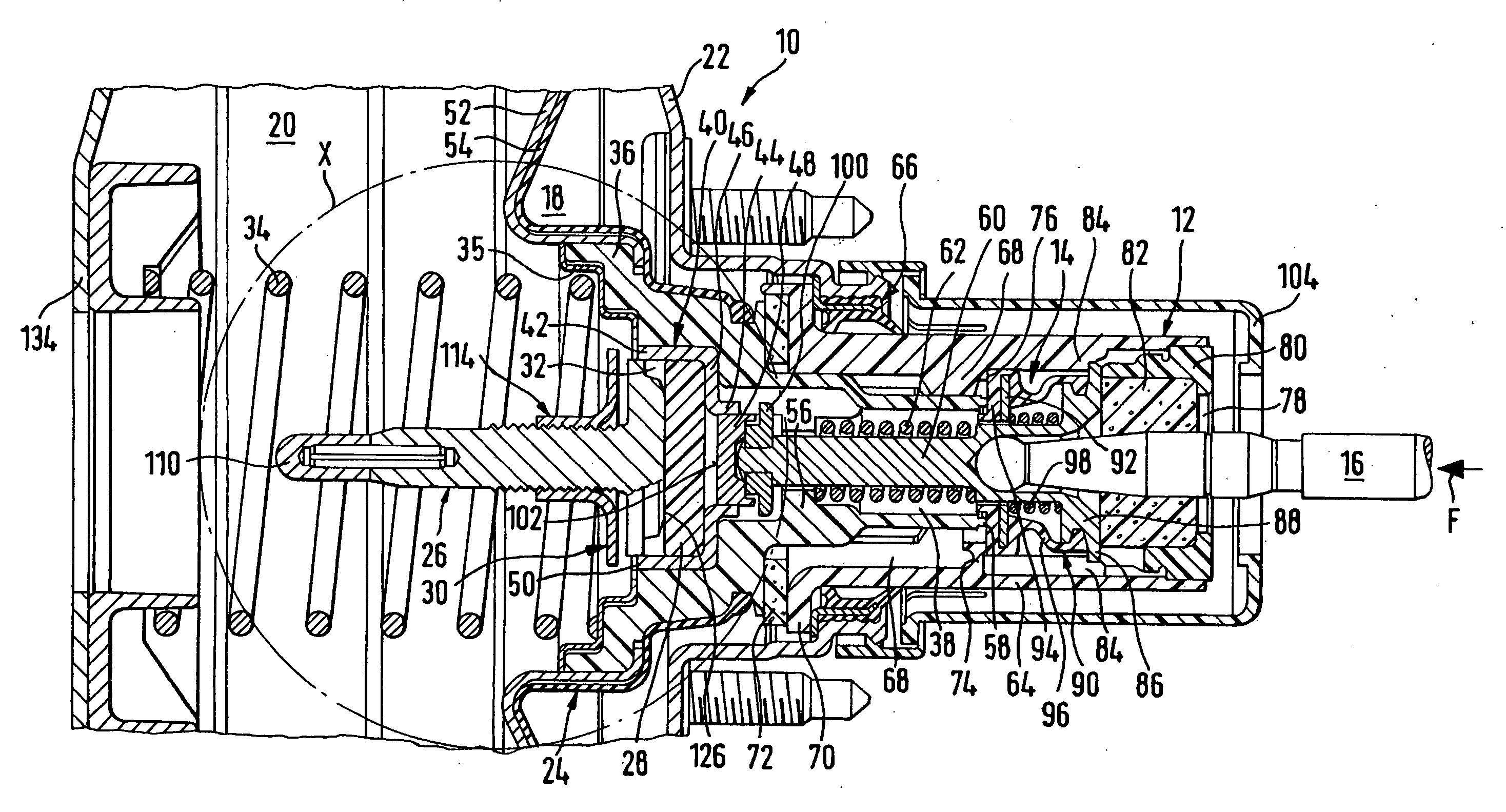
[0039] At this point it should first of all also be noted in connection with the drawings that all the rubber-like elastic components of the vacuum servo brakes shown have been illustrated in the undeformed condition, to simplify the illustration.

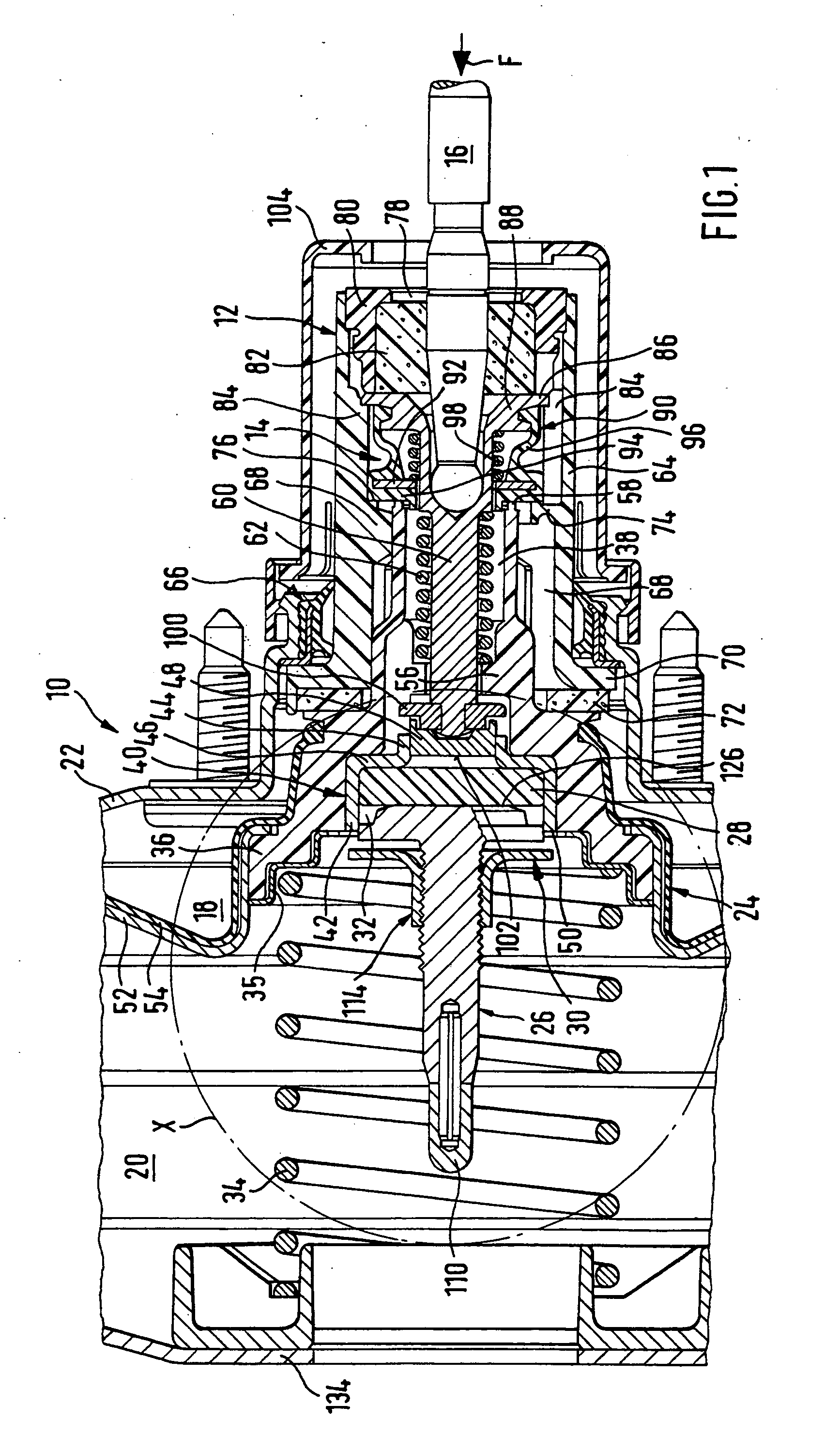
[0040]FIG. 1 shows a vacuum servo brake 10 with no response travel, of a booster brake system for motor vehicles, which may be connected on its left-hand side as seen in FIG. 1, that is to say on the output side, to a main cylinder in a serial or tandem arrangement and on its right-hand side as seen in FIG. 1, that is to say on the input side, to a brake pedal. The main cylinder, which is connected to the wheel brake cylinders in conventional manner, and the brake pedal are constructed as known in the prior art and are not illustrated in the figures, for reasons of clarity. The vacuum servo brake 10 itself is only shown to the extent that appears necessary to understand the present invention.

[0041] The vacuum servo brake 10 has as the inp...


PUM


Abstract

A vacuum servo brake has an input member by which a valve arrangement may be acted upon at an input force to connect a working chamber selectively to the outside or to a vacuum chamber (separated from the working chamber by a piston which may be brought into operative connection with a main cylinder via an output member to generate a braking pressure). Provided on the piston is an elastomeric reaction member through which a reaction force may be applied to the input member. The output member has a stop which, with a predetermined input force, abuts against the working piston to alter an amplification ratio of the brake. Arranged adjacent to the reaction member is at least one volume take-up means into which part of the reaction member may be displaced in the event of the vacuum servo brake being actuated. Furthermore, the stop is preferably of resilient construction.

Description

FIELD OF THE INVENTION [0001] The present invention relates to a vacuum servo brake for a booster brake system for motor vehicles, as used in large numbers in the automotive industry. BACKGROUND OF THE INVENTION [0002] In a booster brake system in a motor vehicle, the energy required to generate the braking force comes from at least one energy supply device and—unlike the situation with a power-brake system—the physical force of the driver of the motor vehicle. To convert this energy, a vacuum servo brake connected between the brake pedal and the main cylinder in a serial or tandem arrangement is typically used. The vacuum servo brake has a working cylinder which is brought into operative connection with the main cylinder via an output member and separates a vacuum chamber from a working chamber. The vacuum servo brake furthermore has a control valve which is brought into operative connection with the brake pedal via an input member and selectively connects the vacuum chamber and th...

Claims


Application Information

Patent Timeline
IPC IPC(8): B60T13/52B60T13/573B60T13/56B60T13/57B60T13/575
CPCB60T13/575B60T13/57
Inventor SCHRAMM, HORSTSEIDI, ROLFHOCH, JOACHIM
Owner FTE AUTOMOTIVE GMBH & CO KG
Why Eureka
Try Eureka