
Method for holding substrate in vacuum, method for manufacturing liquid crystal display device, and device for holding substrate

a technology of liquid crystal display device and substrate, which is applied in the direction of conveyors, instruments, films/foil adhesives without carriers, etc., can solve the problems of adhesive agent remaining on the substrate, adhesive sheet cannot be detached from the substrate, and the vacuum suction method cannot be used to hold the upper substrate, etc., to achieve the effect of easy substrate position registration

Active Publication Date: 2005-08-04
AIMECHATEC LTD
View PDF6 Cites 31 Cited by
  • Summary
  • Abstract
  • Description
  • Claims
  • Application Information

AI Technical Summary

Benefits of technology

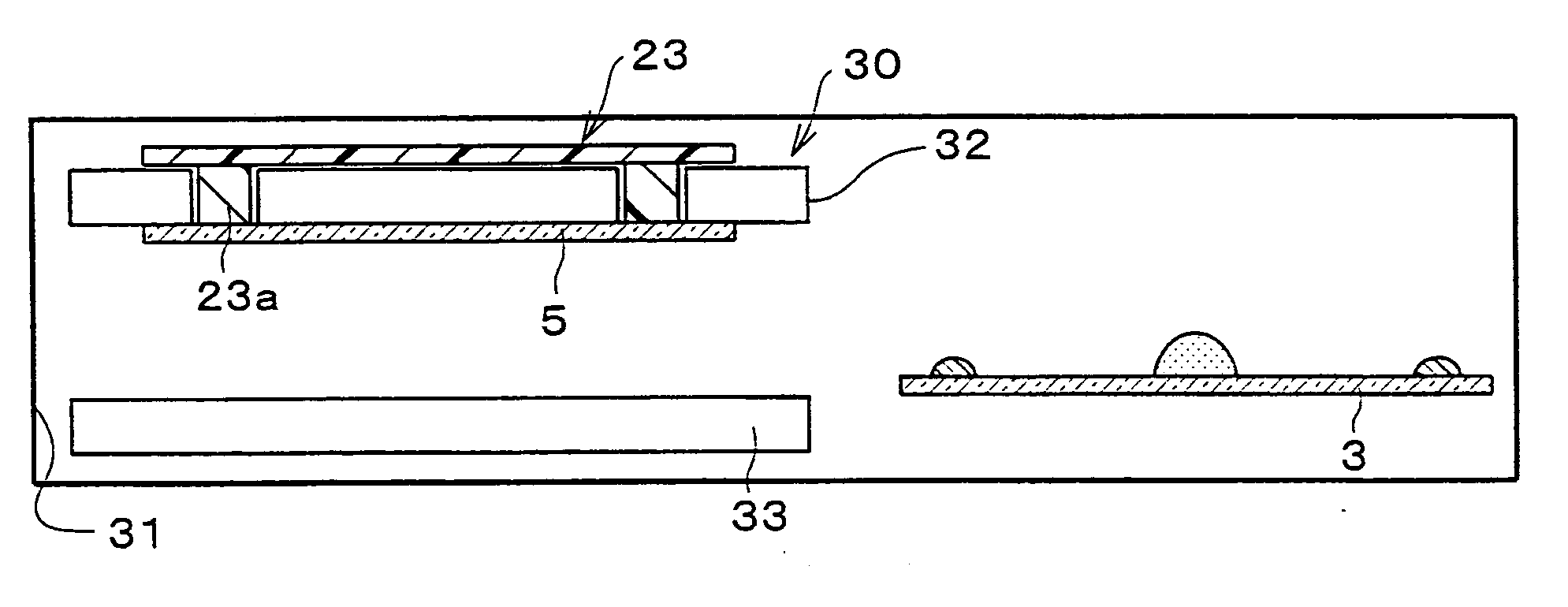
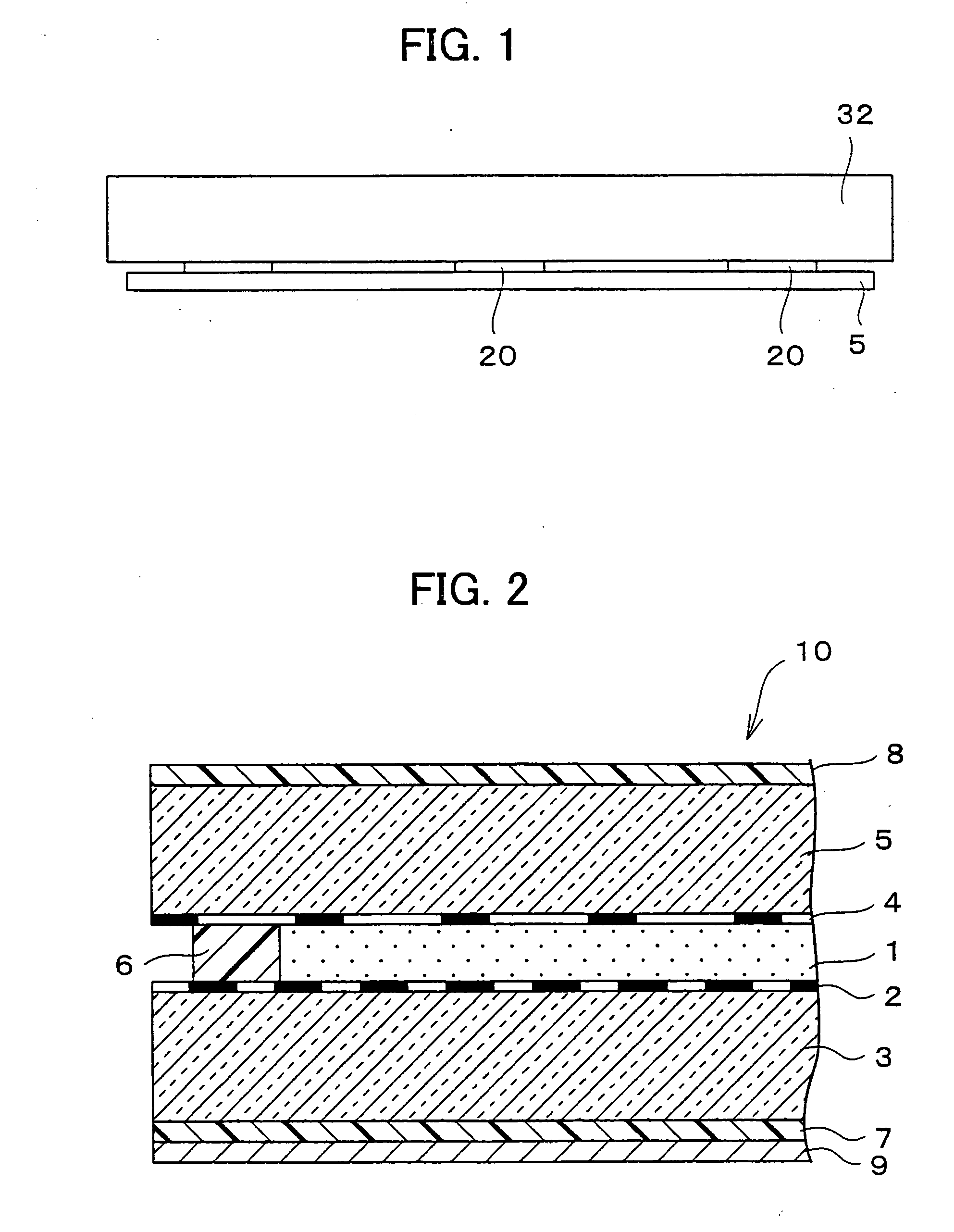
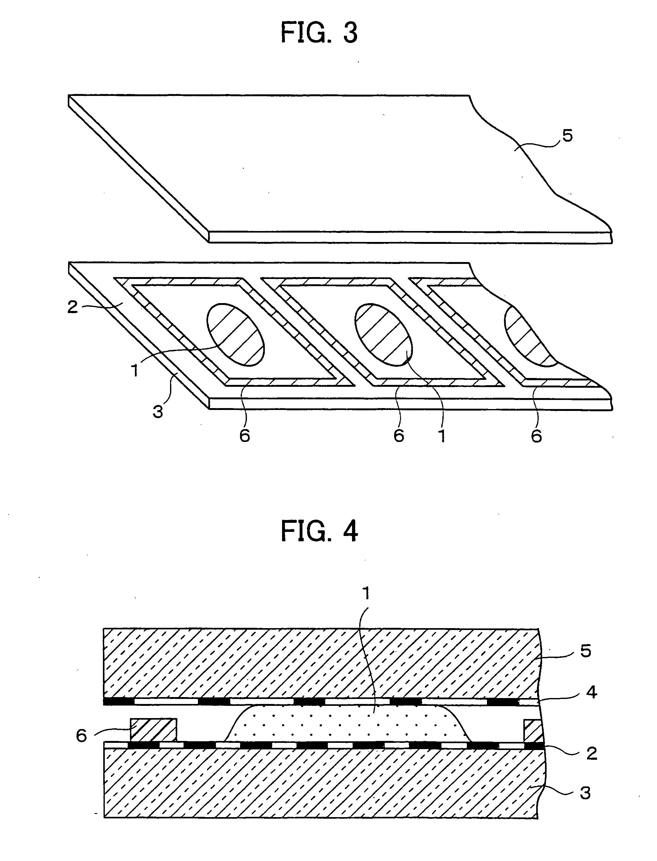
[0021] The present invention therefore provides a method for holding a substrate in a vacuum, a method for manufacturing a liquid crystal display device, and the substrate assembly device, whereby an adhesive agent is prevented from remaining on the substrate, and the adhesive pad and the adhesive sheet can be detached with ease from the substrate after assembling the substrates.
[0049] A substrate holding device of the present invention includes: an adhesive member for holding a substrate, the adhesive member having flexibility and adhesion, and being able to maintain its shape after a release of applied external pressure.

Problems solved by technology

Incidentally, when the liquid crystal is dropped and the substrates are assembled in a vacuum as above, the following problems are caused.
First, a vacuum suction method cannot be used for holding an upper substrate, because the injection step is performed in the vacuum device.
However, in cases where the substrate is held by such a tape, there is a problem that the adhesive agent remains on the substrate.
Further, in cases where the adhesion is too strong, the adhesive sheet cannot be detached from the substrate.
This may cause damage on the substrate when the adhesive sheet is detached from the substrate.
This affects the performance and quality of the liquid crystal display panel.
However, because the adhesive tape or the like does not have even thickness, it is impossible to substantially evenly exert pressure over the entire substrates.

Method used


Image

  • Method for holding substrate in vacuum, method for manufacturing liquid crystal display device, and device for holding substrate
  • Method for holding substrate in vacuum, method for manufacturing liquid crystal display device, and device for holding substrate
  • Method for holding substrate in vacuum, method for manufacturing liquid crystal display device, and device for holding substrate

Examples


example 1

[0120] An experiment was carried out to examine the effectiveness of adhesion of the adhesive pad 21 made of unsaturated polybutadiene described in the First Embodiment.

[0121] Firstly, an unsaturated polybutadiene resin (trade name “APR K-11”) of the Asahi Kasei Corporation was used as a material of the adhesive pad 21. Note that the APR is a registered trademark. Generally, this unsaturated polybutadiene is used as a material for a relief in relief printing.

[0122] Then, a negative film, a cover film, the unsaturated polybutadiene resin, and a base film were set in this order on a glass plate of an exposure device, and an upper glass plate was used to apply pressure thereon.

[0123] Next, after forming a back separation layer by back exposure, a relief exposure was carried out to form a sharp relief section (pad section). Then, a portion of the resin which had not been hardened was washed by a washer liquid.

[0124] After that, the unsaturated polybutadiene resin was dried by hot ai...

example 2

[0178] A comparative experiment was carried out to examine whether or not the adhesive sheet 51 and the adhesive pad 52 with their raised portions 61 arranged in a hexagonal pattern as described above in this embodiment can evenly apply pressure on the glass substrates.

[0179] In the experiment, an adhesive sheet 81 (shown in FIG. 20(a) through FIG. 20(c)) was formed as a comparative example to the adhesive sheet 51 (shown in FIG. 14(a) through FIG. 14(c)). As shown in FIG. 20(a), which is a plan view of the adhesive sheet 81, on a lower face (adhesive face) of the adhesive sheet 81, a multiplicity of raised portions 82, each having an elliptical shape, are provided side by side with their long sides directed in one direction. The raised portions 82 are equivalent to the raised portions 61 in the adhesive sheet 51. As shown in FIG. 20(b), which is an enlarged view of FIG. 20(a), each of the raised portions 82 has a protruding wall which forms a closed ring. That is, in the adhesive ...

example 3

[0185] Further, an adhesive sheet 91 (shown in FIG. 21(a) through FIG. 21(c)) was formed as another comparative example of the adhesive sheet 51 (shown in FIG. 14(a) through FIG. 14(c)). As shown in FIG. 21(a), which is a plan view of the adhesive sheet 91, a multiplicity of raised portions 92 were provided on a lower face (adhesive face) of the adhesive sheet 91. The raised portions 92 are equivalent to the raised portions 61 of the adhesive sheet 51. As shown in FIG. 21(b), which is an enlarged view of FIG. 21(a), each of the raised portions 82 has a circular ring shape. As shown in a cross sectional view taken along zz-zz in FIG. 21(b), a through hole 93 for vacuum suction was provided in a central portion of each of the raised portions 92, penetrating through the adhesive sheet 91 in a thickness direction.

[0186] The raised portions 92 were formed with an outer diameter D1 of 3 mm as measured at the highest point of the circular ring, an inner diameter D2 of 2 mm, and a pitch PX...


PUM

PropertyMeasurementUnit
Adhesion strengthaaaaaaaaaa
Flexibilityaaaaaaaaaa
Surfaceaaaaaaaaaa

Abstract

In a method of the present invention for holding a substrate in a vacuum, a glass substrate (5) is held by an adhesive pad (20) or an adhesive sheet, both of which are made from a material containing a diene based resin, whereby an adhesive agent is prevented from remaining on the substrate, and the adhesive sheet can be detached with ease from the substrate after assembling the substrates.

Description

TECHNICAL FIELD [0001] The present invention relates to (i) a method for holding a substrate in a vacuum when two substrates are assembled together in a vacuum, (ii) a method for manufacturing a liquid crystal display device, and (iii) a substrate holding device. BACKGROUND ART [0002] In manufacturing a liquid crystal display panel, two glass substrates with a transparent electrode, a thin film transistor array, and the like need to be assembled together with a sealing material by leaving a very narrow space in the order of several μm between each other, and by filling the space with liquid crystal and sealing it. [0003] Here, conventionally, for example, a method described below is used for filling and sealing the liquid crystal. [0004] Firstly, under ordinary pressure, a sealing material having an opening for injecting the liquid crystal is formed around the periphery of a cell in one of two substrates, and then the two substrates are assembled, pressed, and hardened. Next, the as...

Claims


Application Information

Patent Timeline
IPC IPC(8): C09J7/10G02F1/1333G02F1/1341H01L21/68
CPCB32B37/1292Y10T428/2883B32B2457/20B65G49/061B65G2249/02B65G2249/04B65G2249/045C09J7/00C09J2201/28C09J2409/00G02F1/1333G02F1/1341G02F2001/133302G02F2001/133354G02F2202/28H01L21/6835H01L2924/1017B32B2038/1891Y10T428/24165Y10T428/24355B32B2309/68C09J7/10C09J2301/204G02F1/133302G02F1/133354G02F1/13H01L21/68
Inventor YOKOYAMA, NAOTOMORIMOTO, MITSUAKINAKAHARA, MAKOTOMURAYAMA, TAKAOHIRAI, AKIRAYAWATA, SATOSHI
Owner AIMECHATEC LTD
Learn More