Laser driven ion accelerator

a particle accelerator and accelerator technology, applied in the direction of instruments, heat measurement, beam deviation/focusing by electric/magnetic means, etc., can solve the problems of damage to healthy tissues, high doses of radiation to healthy tissues between the tissue surface and cancer, and physicians using less than optimal doses

Inactive Publication Date: 2005-08-04
LAWRENCE LIVERMORE NAT SECURITY LLC
View PDF13 Cites 86 Cited by
  • Summary
  • Abstract
  • Description
  • Claims
  • Application Information

AI Technical Summary

Problems solved by technology

Due to the inability of current technology to preferentially deposit the radiation at the site of the cancer, healthy tissues between the tissue surface and the cancer also receive high doses or radiation and, therefore, are damaged.
Consequently, physicians use a less-than-optimal dose to reduce the undesirable damage to healthy tissues and the subsequent side effects.
In many cases, this proves to be an unacceptable alternative.

Method used


Image

  • Laser driven ion accelerator
  • Laser driven ion accelerator
  • Laser driven ion accelerator

Examples


Embodiment Construction

[0016] Disclosed herein are described accelerator systems and methods which may deliver protons and other ions to higher energies in an efficient manner. The accelerator systems and methods described herein may be in a compact or portable form to increase the flexibility of its use. Exemplary applications of the disclosed accelerator systems and methods may include radiation oncology; ion radiology; ion isotope sources; pion, muon, and neutrino beams sources; and spectroscopic diagnosis (nondestructive or otherwise) of different types of materials. For illustrative purposes, the exemplary embodiments disclosed herein may be used in radiation oncology applications.

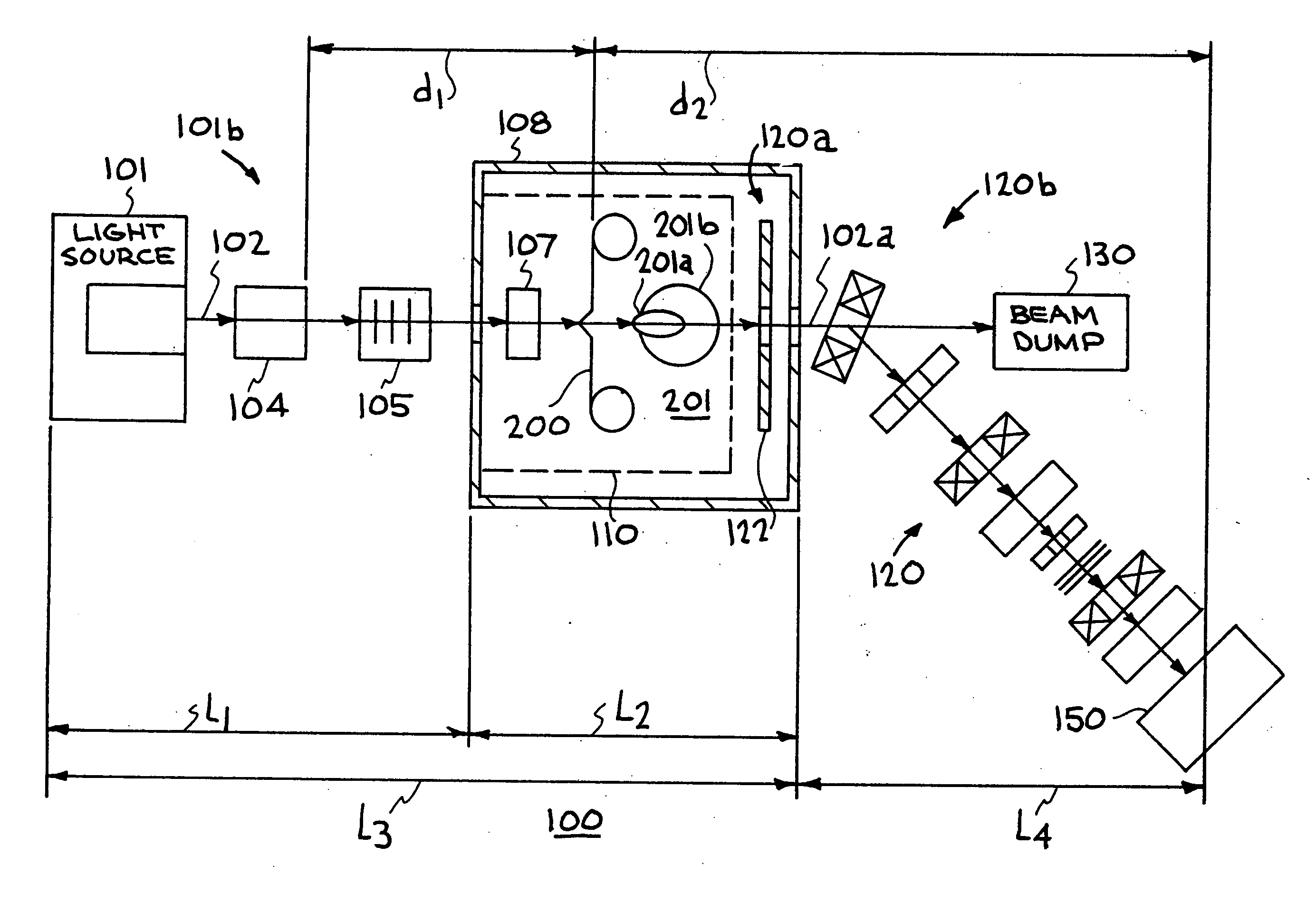
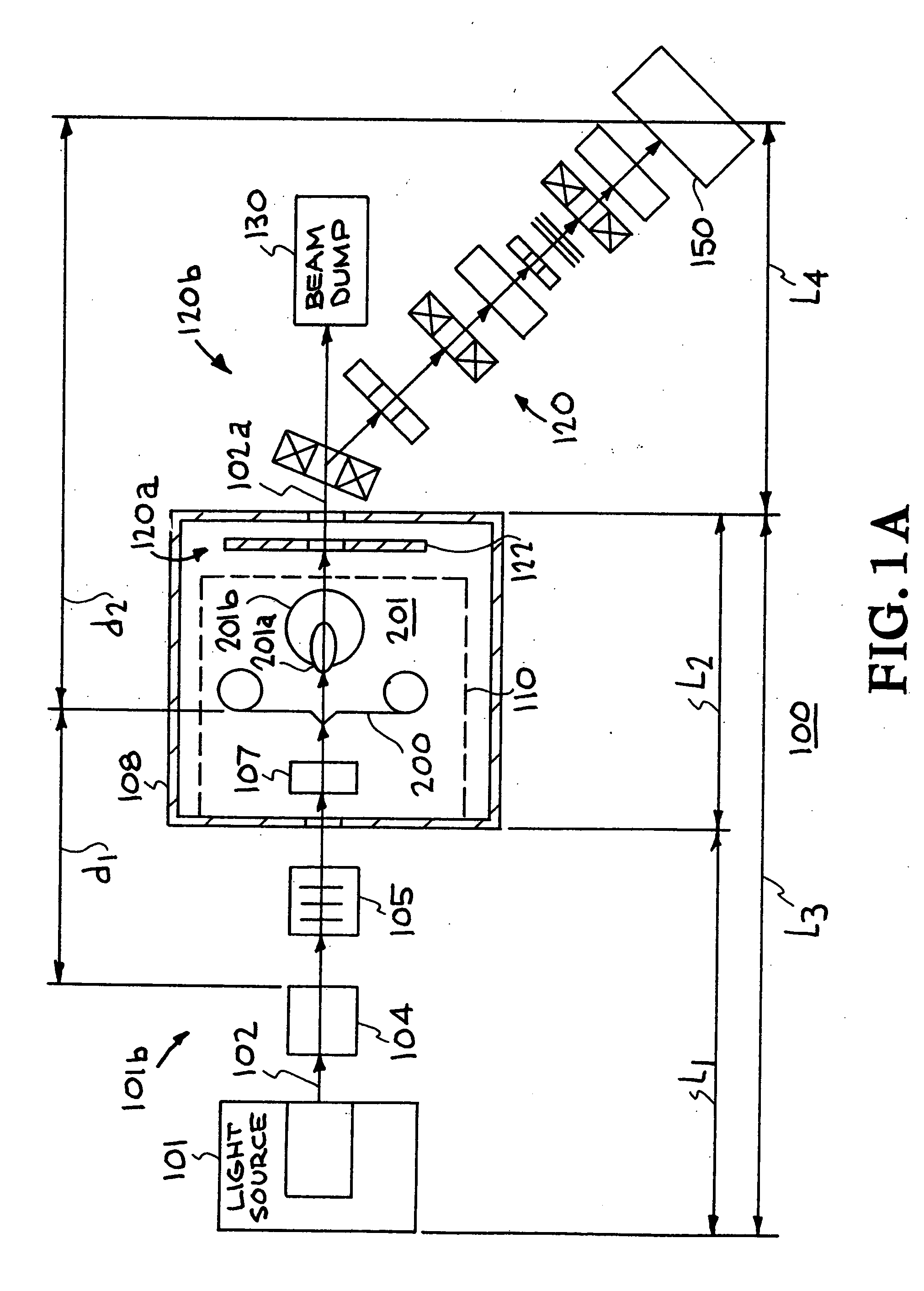
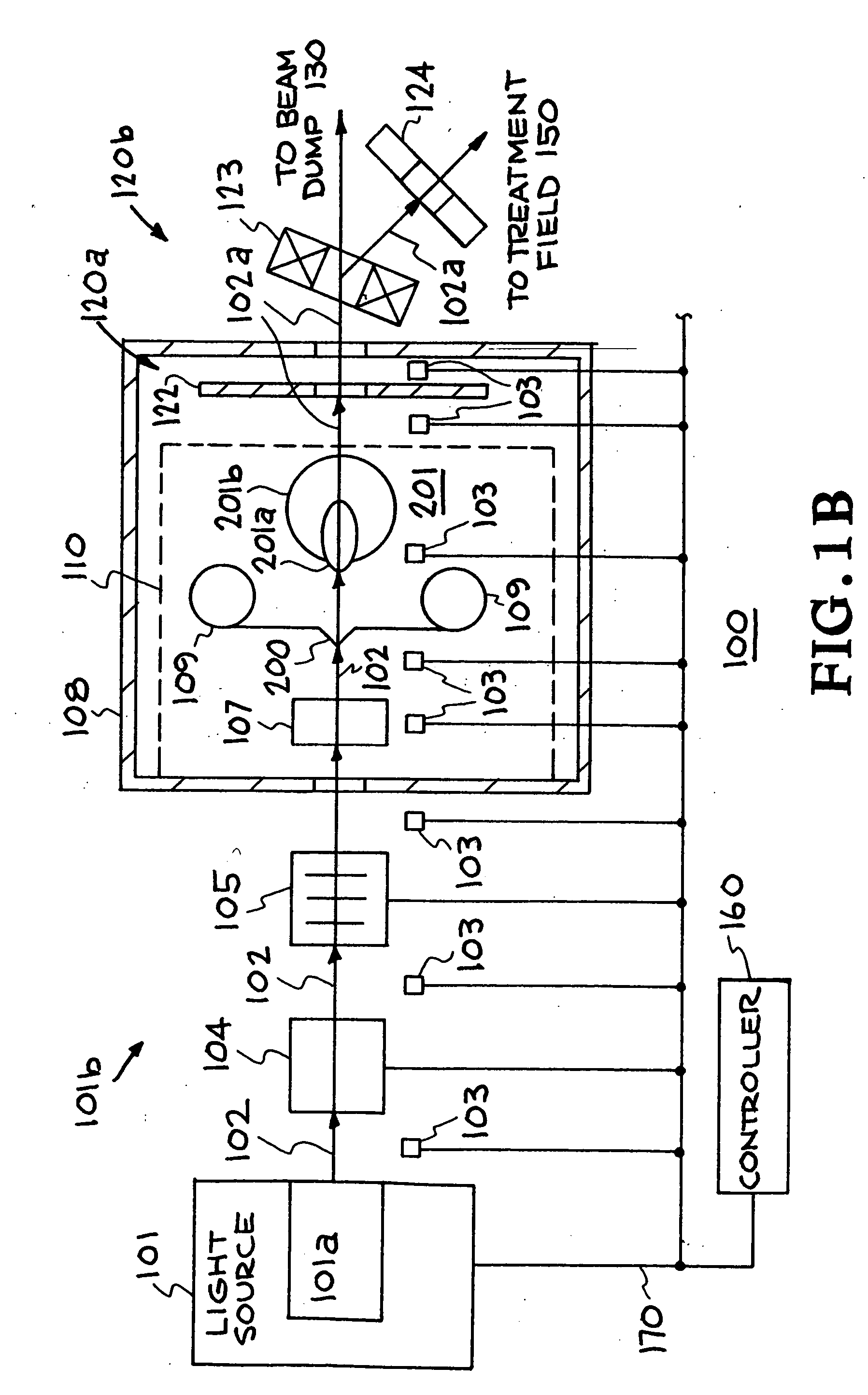
[0017]FIGS. 1A-1E illustrate a schematic view of an embodiment of an accelerating system 100. The accelerating system includes the following components: a light source system (e.g., laser system) 101 producing an energy pulse 102 which travels through a light source guide system 101b to a target system 110 located in a vac...


PUM


Abstract

A system and method of accelerating ions in an accelerator to optimize the energy produced by a light source. Several parameters may be controlled in constructing a target used in the accelerator system to adjust performance of the accelerator system. These parameters include the material, thickness, geometry and surface of the target.

Description

CROSS-REFERENCE TO RELATED APPLICATIONS [0001] This application is a division of application Ser. No. 09 / 757,150 filed Jan. 8, 2001 entitled “Laser Driven Ion Accelerator” by inventor Toshiki Tajima. RELATED APPLICATION [0002] This application relates to U.S. Provisional Application No. 60 / 224,386 filed Aug. 9, 2000, and claims priority thereof.[0003] The United States Government has rights in this invention pursuant to Contract No. W-7405-ENG-48 between the United States Department of Energy and the University of California for the operation of Lawrence Livermore National Laboratory.FIELD OF THE INVENTION [0004] This invention relates to method and apparatus for accelerating particles and, more particularly, to a method and apparatus of accelerating particles to achieve optimal energies. BACKGROUND OF THE INVENTION [0005] Conventional radiation therapy utilizes electron beams and x-rays as a means of treating and controlling cancer. Due to the inability of current technology to pre...

Claims


Application Information

Patent Timeline
Patent Type & Authority Applications(United States)
IPC IPC(8): A61N5/10G21K1/00H05H6/00
CPCA61N2005/1087A61N2005/1088H05H15/00H05H6/00G21K1/003
Inventor TAJIMA, TOSHIKI
Owner LAWRENCE LIVERMORE NAT SECURITY LLC
Why Eureka
Try Eureka