Ion trap time-of-flight mass spectrometer

a mass spectrometer and time-of-flight technology, which is applied in the field of ion trap time-of-flight mass spectrometers, can solve the problems of reducing mass resolution and mass accuracy, spatial spread of ions, and difficult to quickly stop the voltage application at a desired phase, etc., and achieves high detection sensitivity, high mass resolution, and high mass accuracy

Inactive Publication Date: 2009-11-12
SHIMADZU CORP
View PDF20 Cites 11 Cited by
  • Summary
  • Abstract
  • Description
  • Claims
  • Application Information

AI Technical Summary

Benefits of technology

[0029]The ion trap time-of-flight mass spectrometer according to the present invention is capable of differently performing the mass analysis according to the purpose of the analysis, the kind of a sample to be analyzed, the analysis conditions and other factors: For example, the mass analysis may be performed with a high mass resolution and high mass accuracy while maintaining a high detection sensitivity. Alternatively, the analysis may be performed with an even higher mass resolution and mass accuracy if it is particularly important to improve these properties. In the case where the time-of-flight mass analyzer is capable of changing its operation mode between the linear mode and reflectron mode, a high mass resolution and mass accuracy can be achieved in either operation mode.

Problems solved by technology

However, this weakens the capturing action by the radio-frequency electric field, which results in a spatial spread of the ions.
However, a conventional and general analog ion trap uses an inductance-capacitance (LC) resonator to apply an ion-capturing radio-frequency voltage, and such a circuit has a disadvantage in that it is difficult to quickly halt the voltage application at a desired phase.
This might decrease the mass resolution and mass accuracy.

Method used


Image

  • Ion trap time-of-flight mass spectrometer
  • Ion trap time-of-flight mass spectrometer
  • Ion trap time-of-flight mass spectrometer

Examples


example

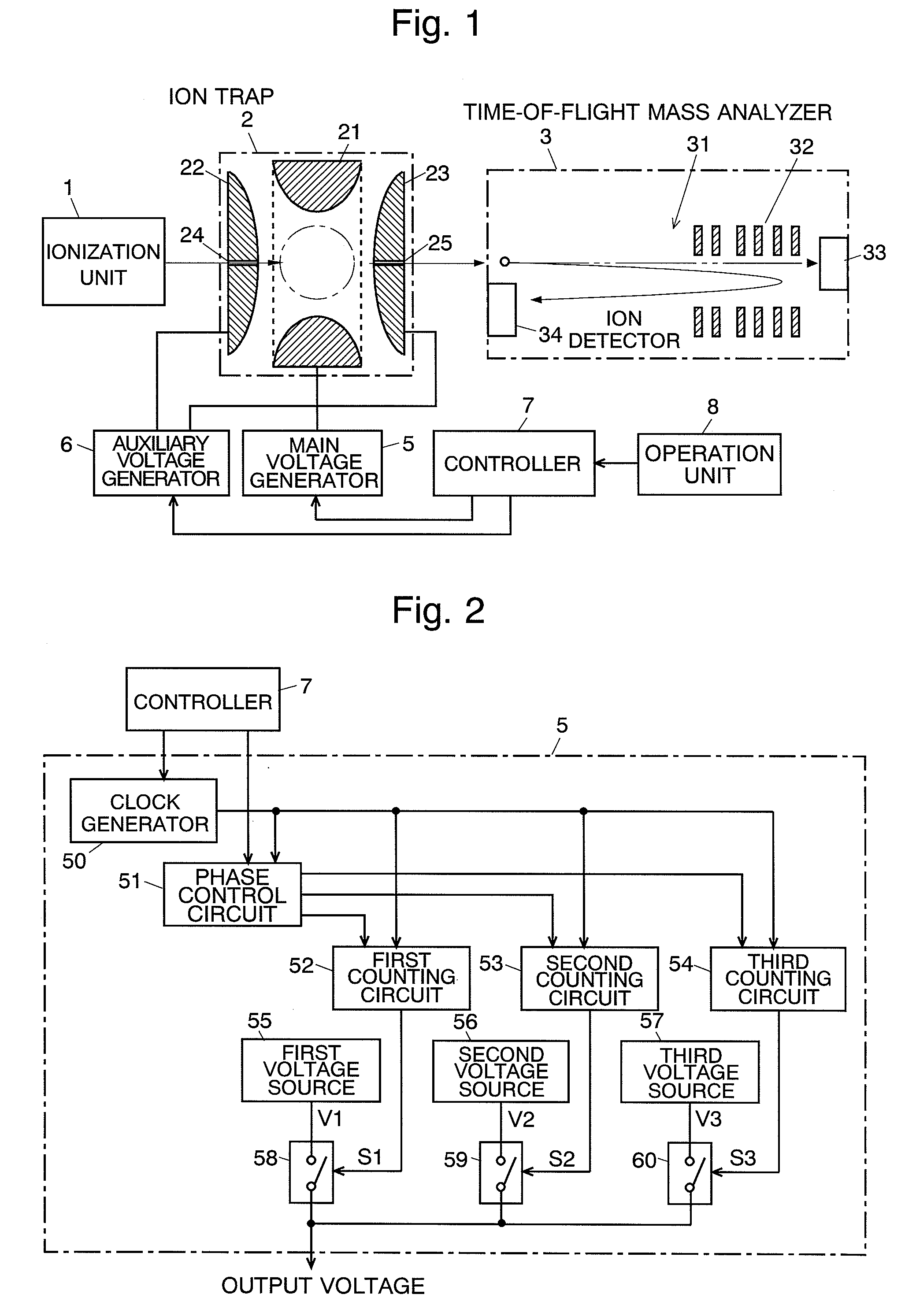
[0071]An experiment using the IT-TOFMS of the embodiment as illustrated in FIG. 1 has been conducted to confirm that it is appropriate that the phase at which the ions are expelled is set to be 1.5π in the reflectron mode as previously described. In this experiment, an electrospray ionization (ESI) method was used as the ionization method in the ionization unit 1, and the time-of-flight mass analyzer 3 was operated in the reflectron mode. As a sample to be analyzed, angiotensin II (amino-acid sequence=[DRVYIHPF], m / z: 1046.5) was used.

[0072]FIG. 5 illustrates the result of an actual measurement of the mass spectrum adjacent to the mass of a monovalent ion of angiotensin II: (a) illustrates a mass spectrum with the phase of 0π, and (b) illustrates a mass spectrum with the phase of 1.5π. Although the peak of the monovalent ion of angiotensin II appears in both spectra, the full width at half maximum (FWHM) of these peaks significantly differ: (a) approximately 0.17Da, and (b) approxim...


PUM


Abstract

The main voltage generator (5) applies a rectangular-wave radio-frequency voltage to the ring electrode (21) in order to capture ions inside the ion trap (2). In the case where the TOFMS (3) is operated in the reflectron mode, the radio-frequency voltage is changed into a constant voltage value when the phase thereof is 1.5π, and a voltage for expelling ions is applied to the end cap electrodes (22, 23) to expel the ions from the exit aperture (25) and introduce them into the TOFMS (3). In this case, since the velocity spread of the ions inside the ion trap (2) is small and so is the spatial spread thereof, a high mass resolution and accuracy can be achieved while assuring a high detection sensitivity. In the case where the TOFMS (3) is operated in the linear mode, the radio-frequency voltage is changed into a constant voltage value when the phase thereof is 0.5π, and then the ions are expelled. In this case, a high mass resolution and mass accuracy can be achieved since the variation of the ions' acceleration, which cannot be converged in the linear mode, can be suppressed.

Description

TECHNICAL FIELD[0001]The present invention relates to an ion trap time-of-flight mass spectrometer in which an ion trap and a time-of-flight mass spectrometer are combined, where the ion trap confines ions by an electric field, and the time-of-flight mass spectrometer separats and detects ions in accordance with the mass by using the flight time difference.BACKGROUND ART[0002]A time-of-flight mass spectrometer (which will be called “TOFMS” hereinafter) generally introduces accelerated ions into a flight space where neither electric field nor magnetic field is present, and separates a variety of ions into every mass (mass-to-charge ratio m / z to be exact) in accordance with the flight time for an ion to reach an ion detector. A TOFMS which utilizes an ion trap as the ion source is conventionally known and called an ion trap time-of-flight mass spectrometer (IT-TOFMS).[0003]As illustrated in FIG. 1, a typical ion trap 2 is what is called a three-dimensional quadrupole type, and is comp...

Claims


Application Information

Patent Timeline
Patent Type & Authority Applications(United States)
IPC IPC(8): H01J49/00
CPCH01J49/424
Inventor IZUMI, HIDEAKITAKESHITA, KENGOOGAWA, KIYOSHI
Owner SHIMADZU CORP
Why Eureka
Try Eureka