Thin, double-wall molded seat frame system

a seat frame and double-wall technology, applied in the field of vehicular seats, can solve the problems of large mass of steel seat frame, large weight of molded seat frame, and large molding thickness of molded seat frame, and achieve the effect of facilitating the incorporation of reinforcement structure and good structural performan

Inactive Publication Date: 2005-08-04
GLANCE PATRICK M +1
View PDF12 Cites 110 Cited by
  • Summary
  • Abstract
  • Description
  • Claims
  • Application Information

AI Technical Summary

Benefits of technology

[0043] Another advantage of the present invention is that the seat frame pan and seat back are formed in two cavity halves, which are molded together to form a closed box section. It is desired that the walls of the two cavities, in each case, are relatively thin (typically about 1 mm) and hence flexible, with internal, molded standoffs reinforcing the outer walls when the two cavities are joined together. Notwithstanding the extremely thin walls, the seat frame pan and seat back provide good structural performance.
[0044] The seat frame pan and seat back can be formed from a number of different manufacturing processes, such as injection molding, twin sheet vacuum forming, vacuum die casting, casting, or compression molding. The seat frame pan may be formed of a number of different materials, such as high density polyethylene, polypropylene, acrylonitrile butadiene styrene, polycarbonate, sheet molding compound, PBT, PET, or metal such as magnesium, zinc alloy, or aluminum. Talc filled HDPE is typical. The seat back can be made of comparable materials.
[0045] As shown in FIG. 10, the formation of th

Problems solved by technology

Front bucket seat pans (a lower seat frame utilized to mount a seat lower cushion) are commonly stamped steel with a steel seat spring suspension, although a technology limitation of steel seating frames is their large mass.
Some seat frames utilize aluminum or magnesium, which has lighter mass, but is more expensive.
A technology limitation of molded seat frames is their relatively large molding thickness, typically about 3 mm with ranges from about 6 to about 2 mm.
The large molding thickness results in a slow molding cycle time, and greater material usage, which directly results in a higher seat frame cost.
This is a techn

Method used


Image

  • Thin, double-wall molded seat frame system
  • Thin, double-wall molded seat frame system
  • Thin, double-wall molded seat frame system

Examples


Embodiment Construction

[0027] A preferred embodiment of a thin, double wall molded seat frame system according to the invention is generally shown in the drawing figures and discussed below.

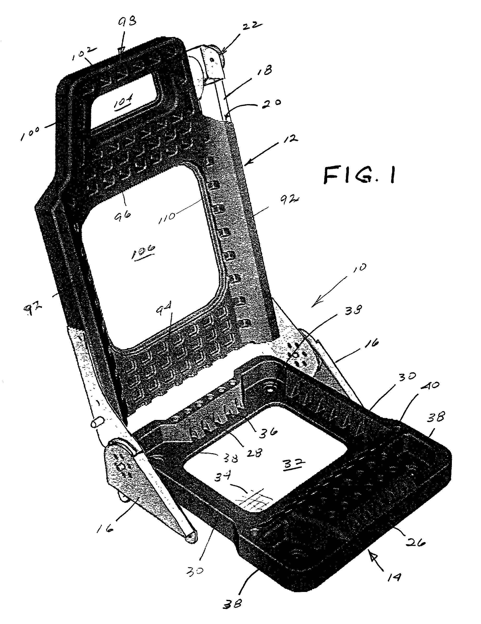
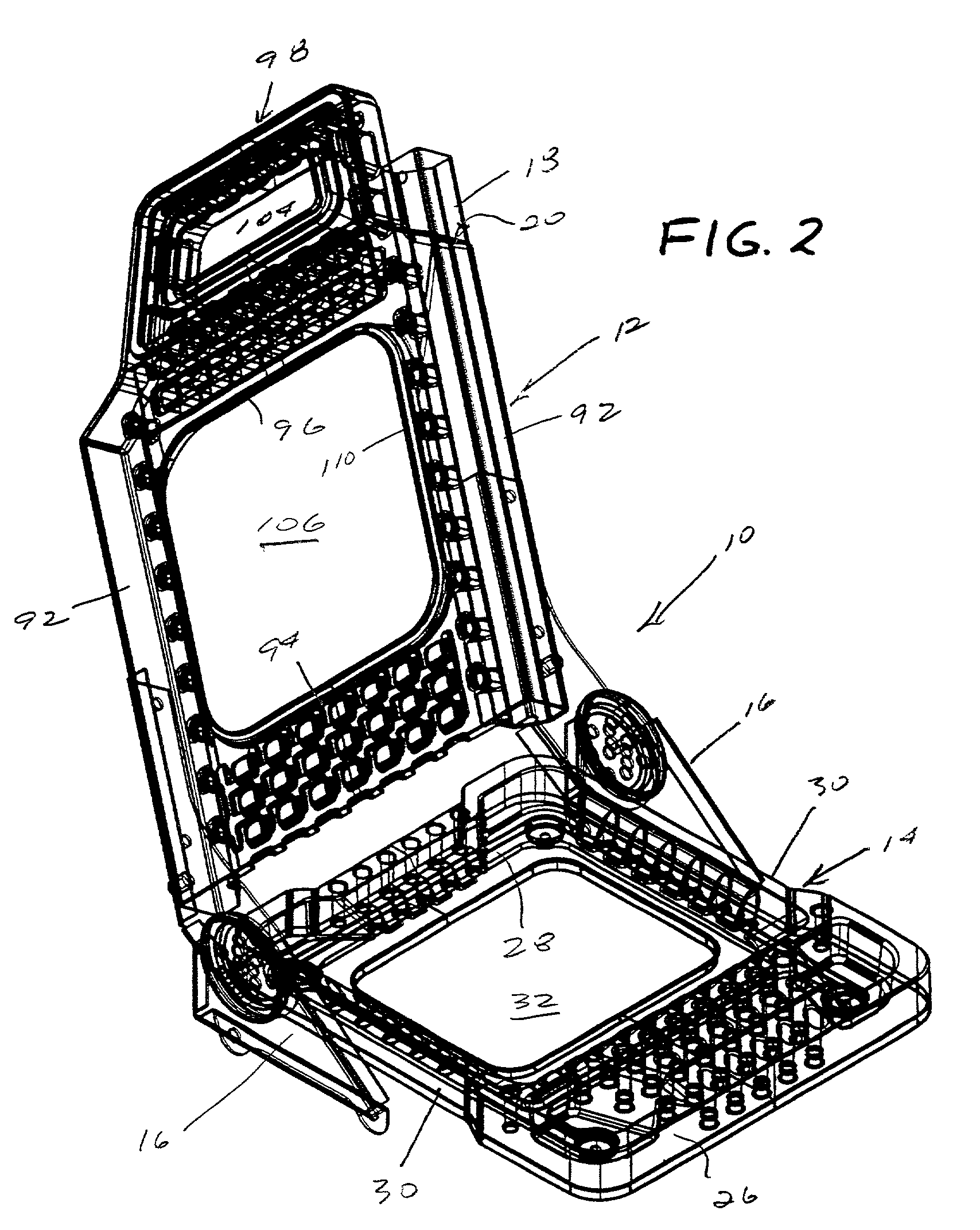
[0028] Referring to the drawings, FIG. 1 is a perspective view of a double wall seat frame assembly 10 constructed in accordance with the present invention. Seat frame assembly includes a seat back 12, a seat pan 14 and a recliner mechanism 16 interconnecting the seat back and seat frame. The recliner mechanism is known.

[0029] A reinforcement tower 18 extends through an internal cavity 20 on one side of the seat back. In FIG. 1, tower 18 is a restraint tower for a seat that incorporates an integral restraint system, wherein the safety belt is attached directly to the seat back. A seat belt retractor housing 22 is mounted on the top of tower 18. Where an integral restraint system is not employed, a conventional reinforcement tower 24 (FIG. 13) is employed instead of the longer restraint tower 18. The shorter reinforce...


PUM


Abstract

A seat frame for a vehicle or other seating comprises a seat back and a seat pan formed of molded double wall members having thin, substantially closed exterior walls and a substantially open interior. The exterior walls include front and back sections having a cavity therebetween, secured together to form a hollow, box beam type of structure. Integrally formed, spaced cup-shaped standoffs extend between the front and back sections between side walls thereof and provide internal reinforcement of the seat member between the side walls. The seat back includes a cavity for a seat back reinforcement member for either a restraint or non-restraint seat.

Description

CROSS-REFERENCES TO RELATED APPLICATIONS [0001] This application is based on and claims the benefit of the filing date of co-pending U.S. Provisional Patent Application Ser. No. 61 / 237,926, entitled Thin, Double-Wall Molded Seat Frame System and filed on Oct. 4, 2000, by Patrick M. Glance and Bradley M. Glance, the disclosure of which is incorporated here by reference.BACKGROUND OF THE INVENTION [0002] The invention relates to vehicular seating generally and more particularly to a new vehicular seat frame. [0003] Today automotive seat frames, for example, are constructed from a number of materials and manufacturing technologies. Most seat frames and seat backs are fabricated from steel tubing. Front bucket seat pans (a lower seat frame utilized to mount a seat lower cushion) are commonly stamped steel with a steel seat spring suspension, although a technology limitation of steel seating frames is their large mass. Some seat frames utilize aluminum or magnesium, which has lighter mas...

Claims


Application Information

Patent Timeline
IPC IPC(8): A47C7/02B60N2/68
CPCB60N2/68
Inventor GLANCE, PATRICK M.GLANCE, BRADLEY M.
Owner GLANCE PATRICK M
Why Eureka
Try Eureka