
Operating method, electronic ballast and system for resonant operation of high pressure lamps in the longitudinal mode

a technology of resonant operation and electronic ballast, which is applied in the direction of modulation, electric variable regulation, sustainable buildings, etc., can solve the problems of insufficient well-balanced segregation, insufficient thorough mixing, and complex implementation of the operating method in the suitable components of the electronic ballas

Inactive Publication Date: 2005-08-04
PATENT TREUHAND GESELLSCHAFT FUR ELECTRIC GLUEHLAMPEN MBH
View PDF5 Cites 6 Cited by
  • Summary
  • Abstract
  • Description
  • Claims
  • Application Information

AI Technical Summary

Benefits of technology

"The present invention provides an improved operating method for metal halide lamps that ensures optimal mixing of the filling components, particularly the metal halides, in different operating positions. The method uses a combination of a radio frequency carrier frequency and an amplitude modulation signal, with a preferred frequency range of about 15 to 20 kHz. The method also includes steps for preparing the lamp, measuring the impedance of the lamp, and determining the optimum frequency setting for mixing the metal halide plasma. The method is particularly suitable for ceramic high-pressure lamps with an aspect ratio of at least 1.5. The invention also provides an electronic ballast that automates the process of achieving the desired color effects and light yield. The method ensures reliable stability in the desired resonance position, even during changes in the internal length of the lamp. The method is simple and easy to implement, and can be automated using the electronic ballast."

Problems solved by technology

This frequency found in this way can, however, be located considerably too high depending on the filling composition of the metal halide filling and the time by which the search procedure is carried out, so that stimulation of the acoustic resonance at the frequency found using the abovementioned method results in inadequate thorough mixing, and does not sufficiently well cancel out the segregation, that is to say the demixing of the plasma.
Furthermore, the implementation of the operating method in suitable components of an electronic ballast is complex.

Method used


Image

  • Operating method, electronic ballast and system for resonant operation of high pressure lamps in the longitudinal mode
  • Operating method, electronic ballast and system for resonant operation of high pressure lamps in the longitudinal mode
  • Operating method, electronic ballast and system for resonant operation of high pressure lamps in the longitudinal mode

Examples


Embodiment Construction

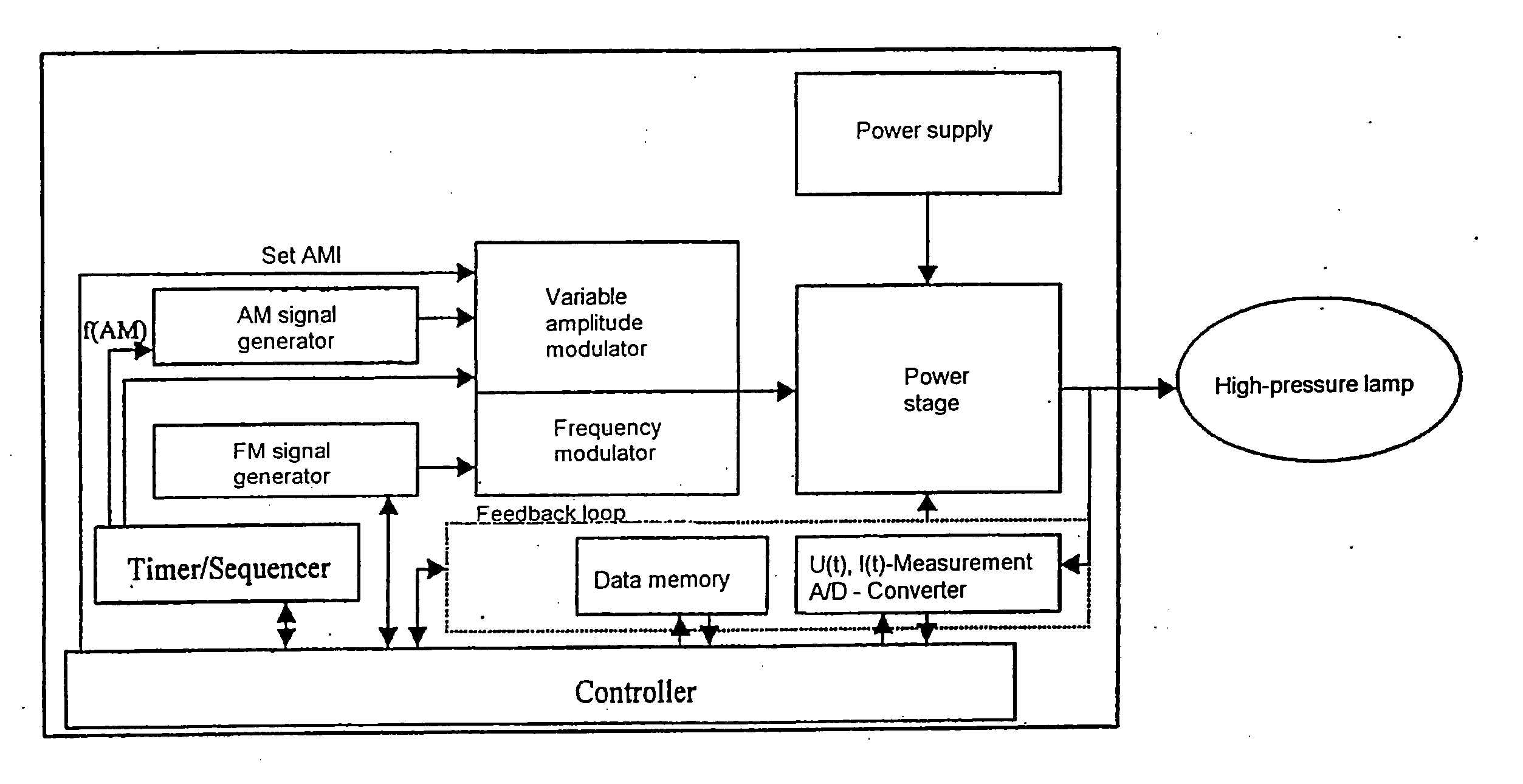
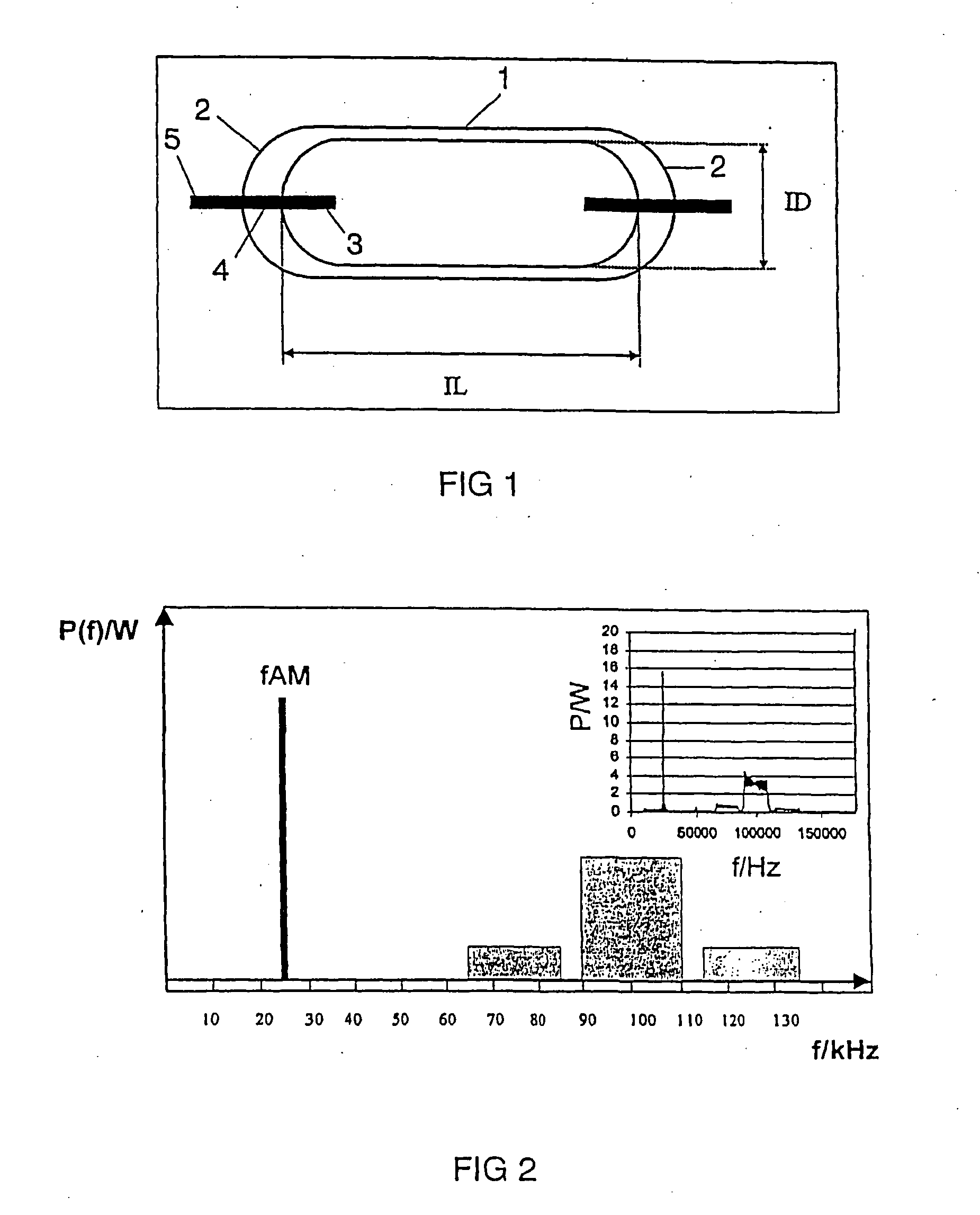
[0120]FIG. 1 shows a schematic illustration of a high-pressure discharge lamp with a relatively high aspect ratio ID / IL. This uses a cylindrical discharge vessel 1 made of ceramic, with a given internal diameter ID and a given internal length IL. Electrodes 3 are arranged at the ends 2 of the discharge vessel and are connected by means of lead-throughs 4 to external power supply leads 5. Typically, the discharge vessel is filled with a buffer gas comprising mercury with argon and metal halides, for example a mixture of alkali and rare-earth iodides as well as thallium iodide. The lamp is operated on an electronic ballast, see FIG. 8, at radio frequency at an acoustically stabilized resonance. The second longitudinal resonance has been found to be particularly worthwhile for this purpose.

[0121] The lamp investigated in more detail is a high-efficiency metal halide lamp with a power of 70 W. The discharge vessel has a maximum axial internal length IL of. 18.7 mm, and an internal diam...


PUM


Abstract

Operating method, electronic ballast and system for resonant operation of high-pressure lamps in the longitudinal mode The operating method is based on the simultaneous use of FM and AM and is distinguished by passing through a number of steps which are used to find an optimum frequency for the AM and, in addition, to define an optimum AM level. An electronic ballast which has a memory module which can be overwritten is used for implementation.

Description

TECHNICAL FIELD [0001] This application is closely related to DE-application no. 10 2004 004 828.2, which was submitted in parallel and which is hereby expressly referred to. [0002] The invention relates to an operating method, an electronic ballast and a system for resonant operation of high-pressure lamps in the longitudinal mode, with an operating method for acoustic resonant operation of metal halide lamps using a radio frequency carrier frequency which is frequency-modulated (FM) by means of a sweep signal and which is amplitude-modulated (AM) at the same time, with a fundamental frequency first of all being set for the AM signal, which is derived from the ith, preferably the second, longitudinal mode. This relates, in particular, to high-pressure discharge lamps with a ceramic discharge vessel, preferably with an aspect ratio of at least 1.5. BACKGROUND ART [0003] U.S. Pat. No. 6,400,100 has already disclosed an operating method, an electronic ballast and a system for resonant...

Claims


Application Information

Patent Timeline
Patent Type & Authority Applications(United States)
IPC IPC(8): H05B41/292H05B41/24
CPCH01J61/827Y02B20/208H05B41/2928Y02B20/00
Inventor STOCKWALD, KLAUS
Owner PATENT TREUHAND GESELLSCHAFT FUR ELECTRIC GLUEHLAMPEN MBH
Learn More