Collapsible wide band width discone antenna

a discone antenna and wide band technology, applied in the field of discone antennas, can solve the problems of difficult deployment of base stations in battlefield scenarios and inability to be easily portable, and achieve the effects of reducing the overall dimension of the antenna, eliminating performance degradation, and reducing the low frequency cutoff of the antenna

Inactive Publication Date: 2005-08-04
SCHILMASS
View PDF8 Cites 18 Cited by
  • Summary
  • Abstract
  • Description
  • Claims
  • Application Information

AI Technical Summary

Benefits of technology

[0017] Also, it has been found that rather than utilizing rods which are not terminated at their ends or interconnected at the periphery of the cone, in the subject invention the distal ends of each of the rods are electrically connected together or bonded by a peripheral ring so as to eliminate ground capacitance effects. What this means is that the antenna when deployed can be deployed over the ground without concern about detuning and works over an infinitely conducting ground or one which is composed of sand, such as in the desert.
[0018] While the utilization of meander lines interposed on the rods to move the low frequency cutoff of the antenna down to, for instance, 30 megahertz, it is possible, utilizing a simple toroidal inductor connected between the feed point of the cone and the feed point of the disc to further reduce the low frequency cutoff of the antenna to as low as 20 megahertz. The result of the toroidal inductor is to reduce the VSWR below 30 megahertz to below 3:1.
[0020] What one has achieved is that, at the point that the fused coax goes through the disc, since it is electrically coupled to the periphery of the aperture through the disc, it has no effect on the antenna. However, because the central conductors of these coaxial cables project through this aperture, as does the remainder of the coax, then one obtains two extra feed points without affecting the tuning of the low frequency band discone antenna.
[0023] What is therefore provided through the utilization of meander line stubs, connecting the distal ends of the skeletal elements and providing the toroidal inductor feed and the availability of feed points above the disc associated with the lowest-frequency band, is that one has a readily deployable and easily collapsible, small, ultra wide-band antenna system which can be deployed by mobile forces with ease to provide communications antennas for mobile base stations.
[0025] In summary, a collapsible discone antenna is provided with an ultra wide band width by providing a collapsible conical skeleton cone, with the rods of the skeleton being provided with meander lines so as to effectively reduce the overall dimensions of the antenna by a factor of 2, with the antenna rods being electrically interconnected at their distal ends so as to eliminate performance degradation due to varying ground conductivities. A specialized feed configuration is used in one embodiment to feed multiple antennas stacked above a low band disc through the utilization of one or more coaxial lines which are wrapped around a ferrite toroid so that they may be passed up through the low-band disc without detuning the low band discone antenna. The use of the toroid inductor between the low-band cone and the low-band disc further reduces the low frequency cutoff of the antenna by markedly decreasing the VSWR at frequencies as low as 20 megahertz.

Problems solved by technology

What will be immediately appreciated is that such a structure is not easily portable and is not deconstructable for transportation in any easy way, making deployment of base stations in battlefield scenarios somewhat difficult.

Method used


Image

  • Collapsible wide band width discone antenna
  • Collapsible wide band width discone antenna
  • Collapsible wide band width discone antenna

Examples


Embodiment Construction

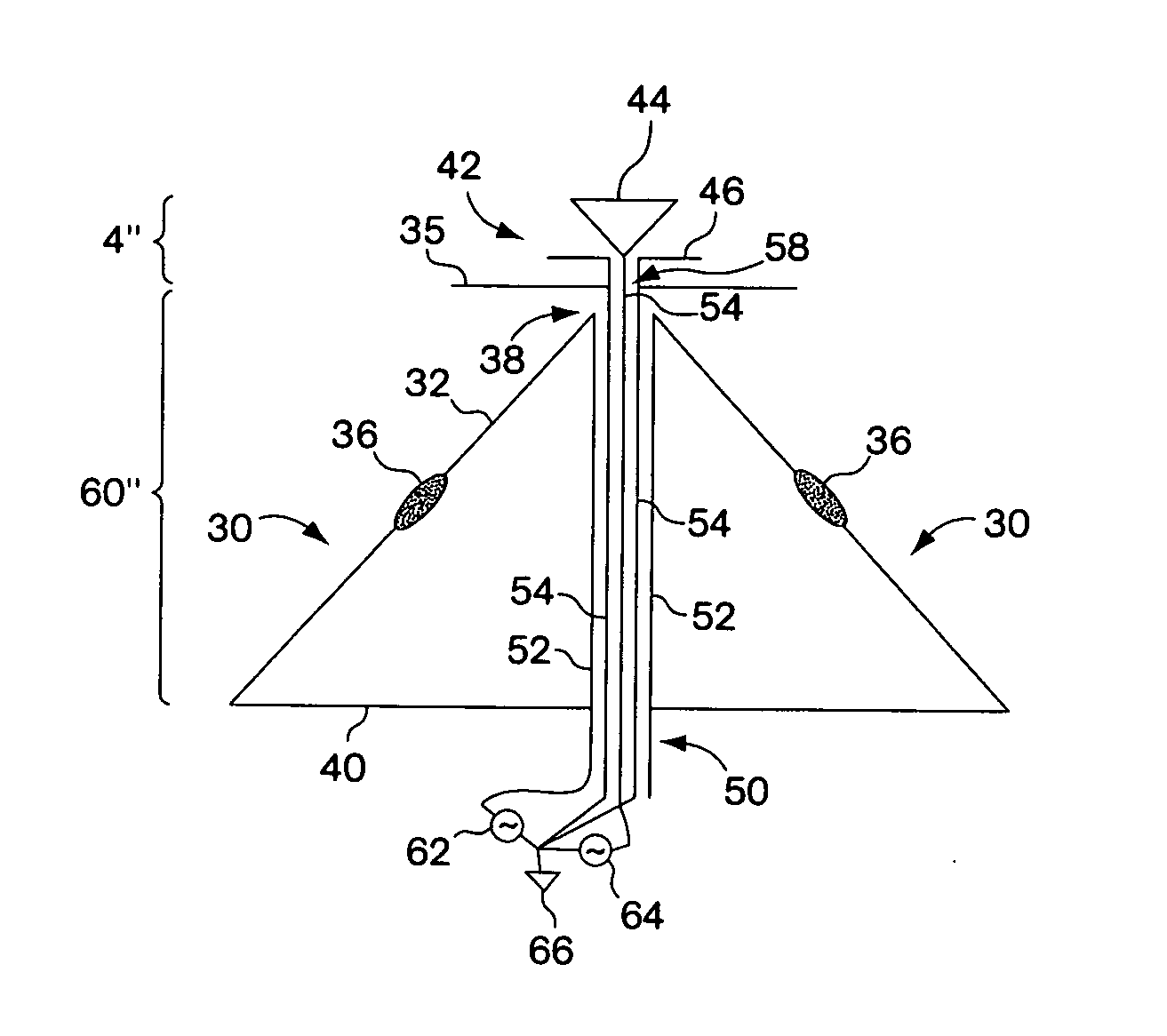
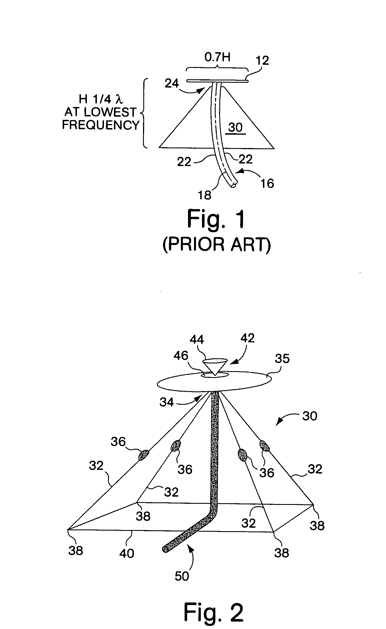
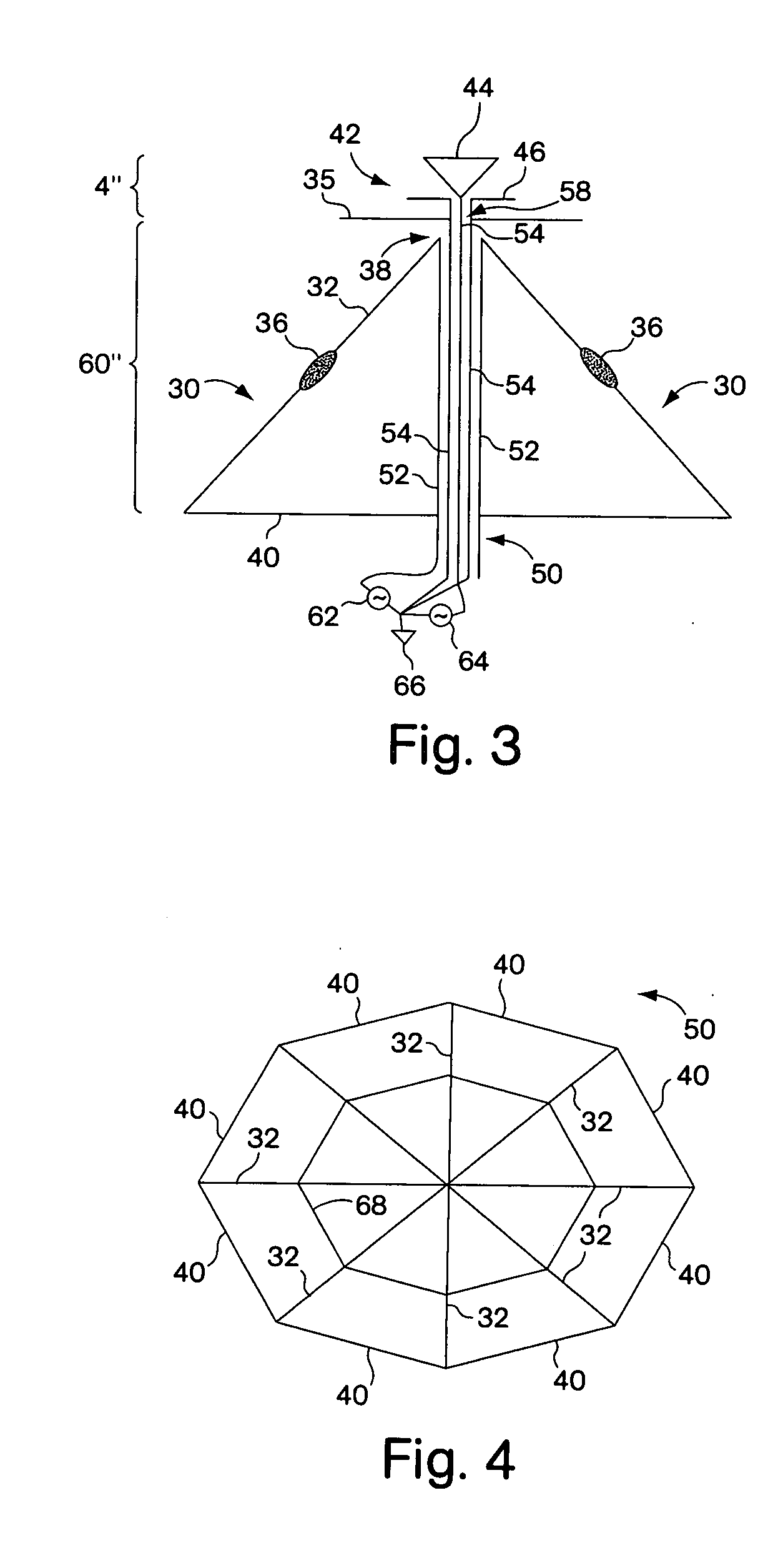
[0038] Referring now to FIG. 1, a typical prior art discone antenna includes a cone 10 and a circular disc 12 positioned above the cone's feed point 14. The antenna is typically fed with a coaxial cable 16 such that the center conductor 18 of the coaxial cable is coupled at the midpoint 20 of the circular disc. The outer braid of the coaxial cable here illustrated at 22 is electrically coupled to an aperture 24 in the apex of the cone to complete the antenna.

[0039] Typically, the height of the antenna is a quarter wavelength at the lowest frequency of the antenna, whereas the diameter of the disc is 0.7H, with H being the height of the cone.

[0040] The discone antenna was invented during World War II to be a wide band antenna whose antenna pattern did not vary significantly with frequency and is a relatively small antenna because it is only a quarter wavelength high. It will be appreciated that the advantage at the time was to be able to have a wide-band antenna whose height was on...


PUM


Abstract

A collapsible discone antenna is provided with an ultra wide band width by providing a collapsible conical skeleton cone, with the rods of the skeleton being provided with meander lines so as to effectively reduce the overall dimensions of the antenna by a factor of 2, with the antenna rods being electrically interconnected at their distal ends so as to eliminate performance degradation due to varying ground conductivities. A specialized feed configuration is used in one embodiment to feed multiple antennas stacked above a low band disc through the utilization of one or more coaxial lines which are wrapped around a ferrite toroid so that they may be passed up through the low-band disc without detuning the low band discone antenna. The use of the toroid inductor between the low-band cone and the low-band disc further reduces the low frequency cutoff of the antenna by markedly decreasing the VSWR at frequencies as low as 20 megahertz.

Description

RELATED APPLICATIONS [0001] This Application claims rights under 35 USC § 119(e) from co-pending U.S. application Ser. No. 10 / 658,186 filed Sep. 9, 2003, the contents of which are incorporated herein by reference.STATEMENT OF GOVERNMENT INTEREST [0002] The invention described herein was made under Contract No. MDA 972.01-9.0019 with the Government of the United States of America and may be manufactured and used by and for the Government of the United States of America for Governmental purposes without the payment of any royalties thereon or therefore.FIELD OF THE INVENTION [0003] This invention relates to discone antennas and more particularly to a method and apparatus for providing an ultra wide band collapsible and foreshortened discone antenna, along with a specialized coaxial feed. BACKGROUND OF THE INVENTION [0004] It has long been the goal to be able to provide a deployable miniaturized wide band antenna which can accommodate a number of frequency bands and more particularly t...

Claims


Application Information

Patent Timeline
Patent Type & Authority Applications(United States)
IPC IPC(8): H01Q1/08H01Q5/00H01Q5/40H01Q9/28H01Q9/46H01Q11/12H01Q13/00
CPCH01Q1/08H01Q5/40H01Q9/46H01Q9/28
Inventor APOSTOLOS, JOHN T.
Owner SCHILMASS
Why Eureka
Try Eureka