Magnetic thin film head, the fabrication method, and magnetic disk

a fabrication method and thin film head technology, applied in nanoinformatics, instruments, record information storage, etc., can solve the problems of unsatisfactory substantial reduction of film formation, achieve higher recording density, reduce noise-after-write and output fluctuation, and improve recording quality

Inactive Publication Date: 2005-08-04
HITACHI GLOBAL STORAGE TECH JAPAN LTD
View PDF6 Cites 0 Cited by
  • Summary
  • Abstract
  • Description
  • Claims
  • Application Information

AI Technical Summary

Benefits of technology

[0014] For successful realization of higher recording density and higher-rate communication in magnetic disk apparatus, there is a necessity to use a magnetic thin film head capable of substantially reducing noise-after-write and output fluctuation.
[0015] As an upper shield film, a permalloy film having a magnetostriction constant λ of −2.0 to −4.0×10⁻⁷ and an Ni content of 80.8 to 81.2 wt % after plating could be provided for reducing the noise-after-write and output fluctuation. However, since the upper shield film tends to be Fe-rich in an initially formed plating layer, this film formation is unsatisfactory for substantially reducing the noise-after-write and output fluctuation in a magnetic disk apparatus scheme for higher-density higher-frequency recording.

Problems solved by technology

However, since the upper shield film tends to be Fe-rich in an initially formed plating layer, this film formation is unsatisfactory for substantially reducing the noise-after-write and output fluctuation in a magnetic disk apparatus scheme for higher-density higher-frequency recording.

Method used


Image

  • Magnetic thin film head, the fabrication method, and magnetic disk
  • Magnetic thin film head, the fabrication method, and magnetic disk
  • Magnetic thin film head, the fabrication method, and magnetic disk

Examples


Embodiment Construction

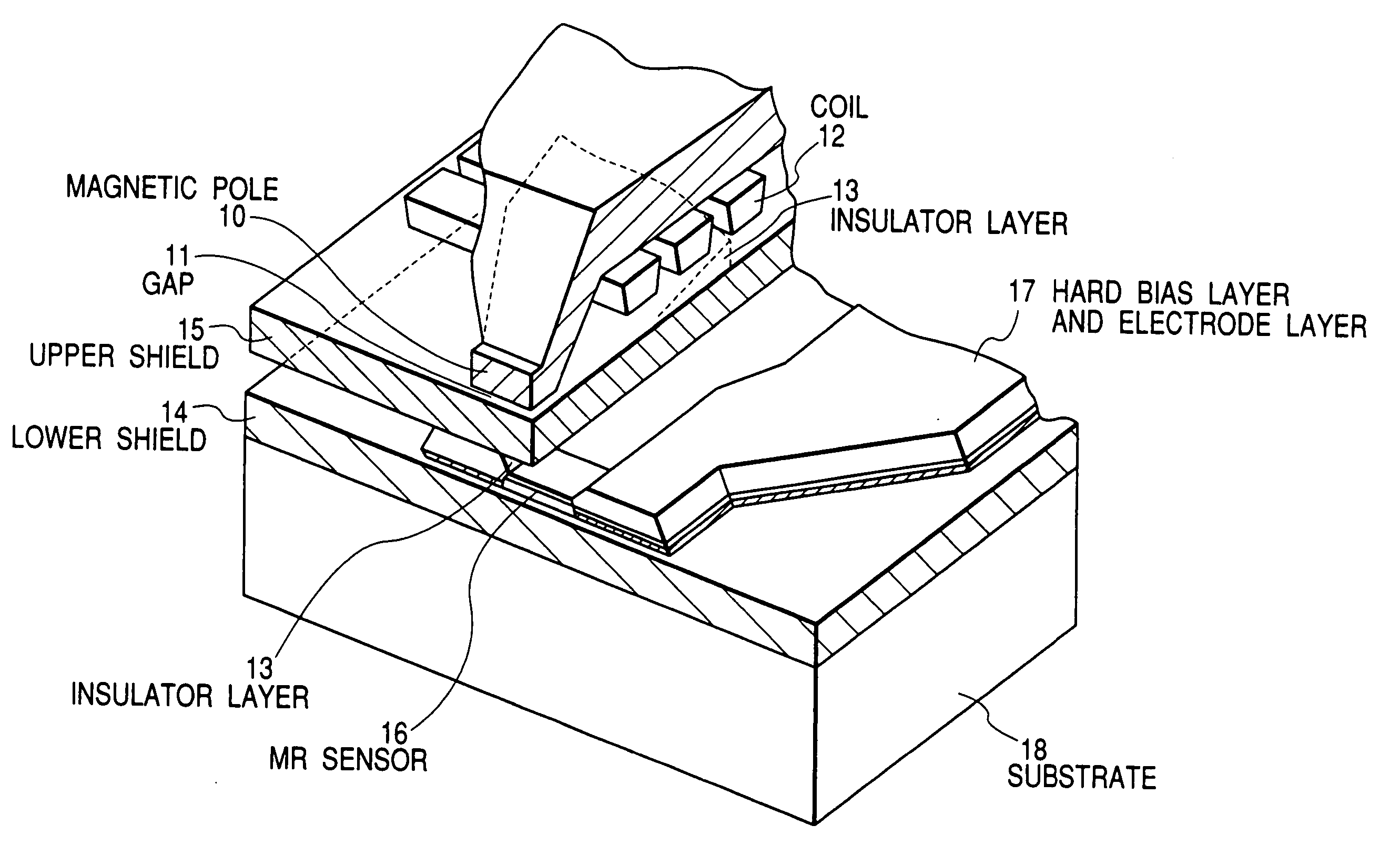
[0039] The present invention concerning a magnetic thin film head and a method of fabricating the same will now be described in detail by way of example with reference to the accompanying drawings. In the following embodiments of the present invention, a glass substrate having a diameter of five inches was used, and as a plating conductive under-layer film, an NiFe permalloy film having a thickness of 0.15 μm and a magnetostriction constant λ of −3 to −4×10⁻⁷ was formed by sputtering technique.

[0040] For electroplating, a bath temperature of 30° C. and a pH value of 3.6 were provided. In bath composition, an Fe+2 metal ion concentration was 0.5 to 1.5 g / l, and an Ni+2 metal ion concentration was 10 to 30 g / l. Sodium benzosulfimide, boric acid, and sodium chloride had concentrations of 1.0 to 2.0 g / l, 20 to 30 g / l, and 20 to 30 g / l, respectively.

[0041] As plating power supply, a constant-current source was used, and for setting time periods and current values of plating, a personal...


PUM

PropertyMeasurementUnit
thicknessaaaaaaaaaa
thicknessaaaaaaaaaa
thicknessaaaaaaaaaa

Abstract

In formation of an upper shield of a magnetic thin film head by electroplating, a current density of electroplating is regulated stepwise with time. Thus, in the upper shield formation, a film composition and magnetic characteristic with respect to the direction of film thickness can be controlled precisely, making it possible to provide a magnetic thin film head featuring significantly reduced noise-after-write and output fluctuation.

Description

BACKGROUND OF THE INVENTION [0001] 1. Field of the Invention [0002] The present invention relates to a plating film fabrication method, and more particularly to a magnetic thin film head fabrication method. Still more particularly, the invention relates to a magnetic thin film head fabrication method using an electroplating technique in which the composition of an initially formed layer in an upper shield of a magnetic thin film head is precisely controlled. Furthermore, the invention pertains to a magnetic thin film head manufactured by the magnetic thin film head fabrication method, and to a magnetic disk apparatus comprising the magnetic thin film head thus manufactured. [0003] The invention is also applicable as a plating film fabrication method other than the magnetic thin film head fabrication method mentioned above, and it is possible to manufacture electronic circuit substrates using the plating film fabrication method according to the invention. [0004] 2. Description of the...

Claims


Application Information

Patent Timeline
Patent Type & Authority Applications(United States)
IPC IPC(8): G11B5/31G11B5/39H01F10/14
CPCB82Y10/00B82Y25/00G11B5/3103G11B5/3113Y10T29/49032G11B5/3967G11B2005/3996Y10T29/49044G11B5/3163
Inventor OIKAWA, GENKOJIMA, SHUICHISAITO, HARUNOBUSAIKI, NORIYUKIKAGAWA, MASAYASUKONDO, AKIRAISHIKAKE, KENJISHIINA, HIROMI
Owner HITACHI GLOBAL STORAGE TECH JAPAN LTD
Why Eureka
Try Eureka