Electronic component cooling apparatus

a technology of electronic components and cooling apparatuses, which is applied in the direction of domestic cooling apparatus, semiconductor/solid-state device details, instruments, etc., can solve the problems of undesirable cooling air flow of electric fans, and achieve the effects of reducing coolant leakage and evaporation, enhancing mechanical strength, and restricting the deformation of outer wall portions

Active Publication Date: 2005-08-04
SANYO DENKI CO LTD +1
View PDF19 Cites 43 Cited by
  • Summary
  • Abstract
  • Description
  • Claims
  • Application Information

AI Technical Summary

Benefits of technology

[0046] In a system including the radiator (path in which the coolant is circulated), the coolant is preferably contained at a pressure lower than an atmospheric pressure. This arrangement ensures that if an ambient temperature rises, the coolant pressure increases only to a level at which the system is not damaged.
[0047] Each outer wall portion of the upper and the lower tanks can be integrally formed with one or more reinforcing ribs for enhancing mechanical strength. These reinforcing ribs can restrict the deformation of the outer wall portions of the upper and lower tanks which is caused by fluctuation of pressure in the radiator and of volume of the coolant.
[0048] Generally, the coolant inlet and coolant outlet of the radiator, the coolant inlet and coolant outlet of the heat sink and a liquid inlet and liquid outlet of the pump are provided with outwardly extending tube connection cylindrical pipes. In this case, end portions of a flexible tube are fitted over outer circumferential parts of the two associated tube connection cylindrical pipes. It is thus preferred that the outer circumferential part of each of the tube connection cylindrical pipes be formed with one or more edge-forming projections each of which has a inclined surface increasing in diameter from a front end side toward a base portion side of the tube connection cylindrical pipe, and with an edge-forming surface extending from a tip of the inclined surface toward the tube connection cylindrical pipe to form an edge that bites into an inner wall of the tube between the inclined surfaces. As the tube is fitted over the tube connection cylindrical pipe, the edges of the edge-forming projections bite into the inner wall of the tube, securely locking the tube. Therefore, a hose band conventionally required for secure connection is not required. Further, since the edges of the edge-forming projections on the tube connection cylindrical pipe bite into the inner wall of the tube, there is no gap between them, significantly reducing coolant leakage and evaporation from the connected portion. The tube is preferably formed of a material which has high heat resistance, chemical resistance and weatherability and which has little flexibility and elasticity. At present a preferable tube is a plastic tube formed of fluororesin in particular. If a tube is formed of fluororesin with a low permeability to water, it can prevent the coolant from passing through its wall, and thereby the volume of coolant from decreasing. A main part of the tube has formed in its outer circumferential part a spiral groove extending longitudinally of the tube or bellows-like grooves. This arrangement facilitates a tube bending during the heat sink mounting process even if the tube has little flexibility or elasticity.
[0049] The portions to be bended of the tube may be bended by forming technique before mounted. If the tube is bended by forming technique before mounted, the tube does not have to be forcibly bended when mounted. Consequently the tube can avoid the reduction of its cooling performance which is caused by an extreme decrease of a cross-sectional area of the tube at a bended portion. Additionally, since the tube is bended by forming technique before mounted, a restoring force is not generated in the tube. Therefore the tube and surrounding components such as an electricity substrate in the system can avoid interfering each other.
[0050] A gasket of an elastic material such as sponge and rubber may be interposed between a peripheral portion of the surface of the radiator on the side not facing the electric fan and a support portion so that, when the radiator is secured to the support portion with the gasket interposed therebetween, an air tightness can be enhanced. However, if the gasket is attached to an arbitrary position, a deformed gasket may contact the heat-radiating surface of the heat-radiating portion, reducing an air inflow area of the heat-radiating surface and degrading the cooling performance. Depending on the deformation of the gasket, its contact with the support portion may deteriorate, resulting in a poor air tightness. To solve these problems, the radiator is preferably attached with gasket support members that supports the gasket keeping the gasket out of contact with the heat-radiating portion and which restricts the deformation of the gasket elastic material in such a manner that the gasket, when pressed against the support portion, can be brought into stable, tight contact with the support portion. The use of the gasket support members eliminates the possibility of the gasket is installed at positions where the cooling performance may be affected. Further, since the gasket support members ensure that the gasket is always deformed in a predetermined shape, a degradation of air tightness can be prevented. The gasket support members are preferably mounted removably on the radiator so that they can be removed when the gasket is not needed.
[0051] With this invention, not only can an electronic component that generates a large amount of heat be water-cooled (or liquid-cooled) to a sufficient level but the electric pump can also be installed inside a planar structure of the radiator. This in turn offers an advantage that an overall size of the electronic component cooling apparatus can be reduced without significantly degrading the cooling performance.

Problems solved by technology

In making the most of the function of the radiator to cool the coolant, an idea of putting in front of the heat-radiating portion of the radiator an object that hinders the flow of cooling air generated by the electric fan is considered undesirable by a person skilled in the art.

Method used


Image

  • Electronic component cooling apparatus
  • Electronic component cooling apparatus
  • Electronic component cooling apparatus

Examples


Embodiment Construction

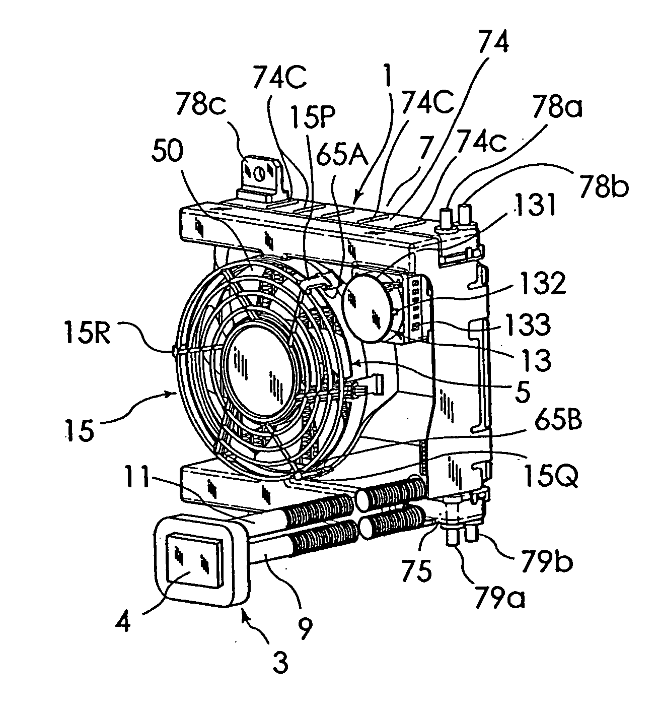
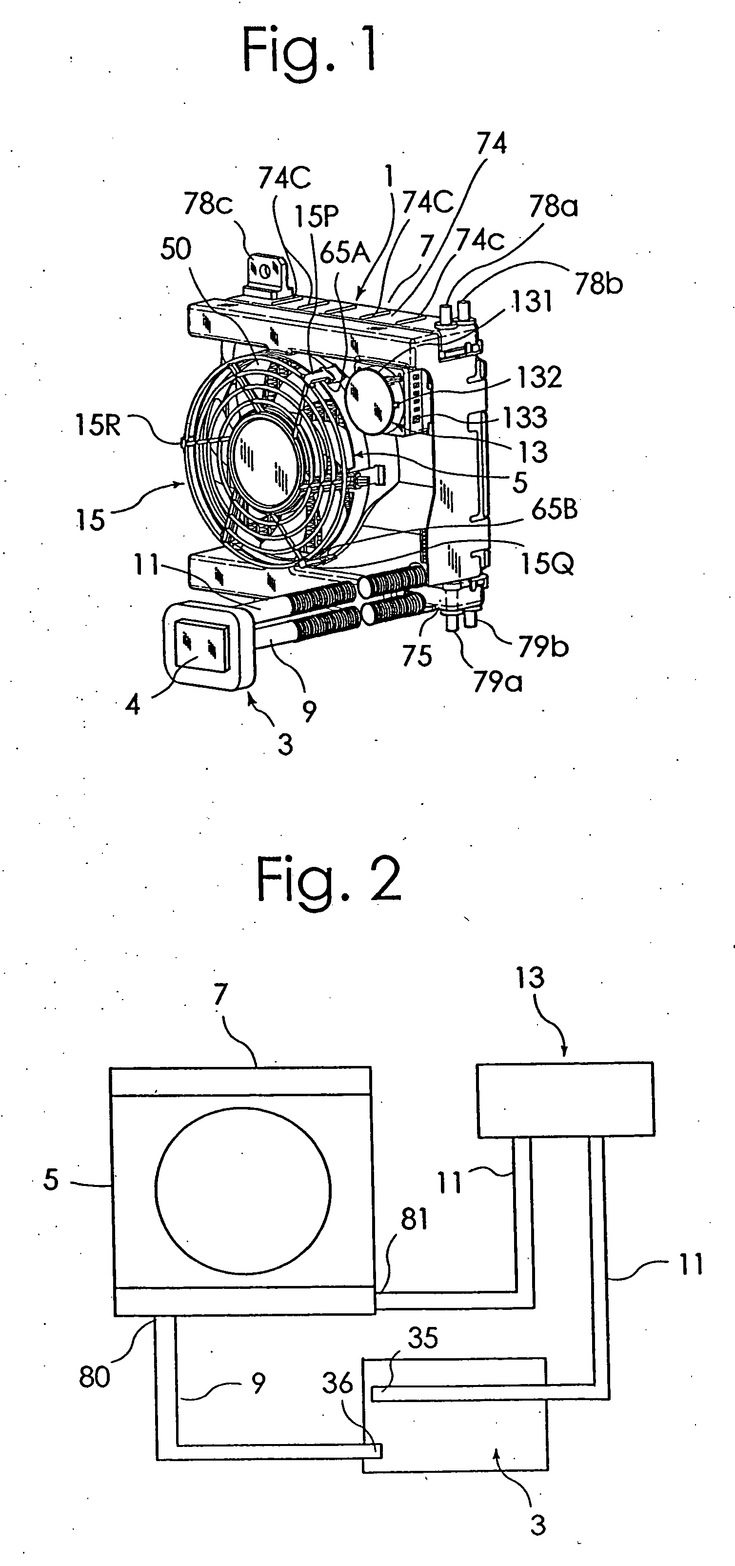
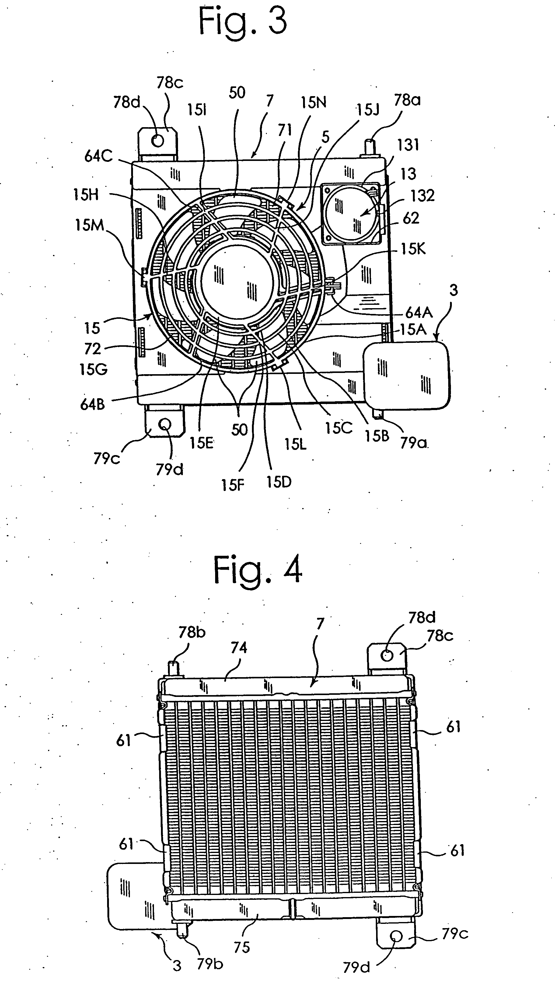
[0085] One embodiment of an electronic component cooling apparatus according to this invention will be described in detail by referring to the accompanying drawings. FIG. 1 is a perspective view of one example embodiment of an electronic component cooling apparatus 1 according to this invention. FIG. 2 is a block diagram showing flow paths in this embodiment. FIG. 3 to FIG. 8 are a front view, a rear view, a right side view, a left side view, a plan view and a bottom view of this embodiment. FIG. 9A is a front view of an electric fan 5 and FIG. 9B is a rear view of the same. FIG. 11 and FIG. 12 are a front view and a right side view, respectively, of a radiator.

[0086] As shown in FIG. 1 to FIG. 8, this electronic component cooling apparatus 1 includes a water-cooled heat sink 3 having a coolant path therein; a radiator 7 cooled by the electric fan 5; and an electric pump 13 to apply a moving energy to a coolant to circulate the coolant between the heat sink 3 and the radiator 7. As...


PUM


Abstract

A small water-cooling type electronic component cooling apparatus is provided. The electronic component cooling apparatus comprises a so-called water-cooling heat sink 3 , a radiator 7 cooled by an electric fan 5 , first and second coolant paths 9, 11 for circulating a coolant between the heat sink 3 and the radiator 7 , and an electric pump 13 to supply a moving energy to the coolant. The electric pump 13 is arranged at a position facing the heat-radiating portion of the radiator 7.

Description

FIELD OF THE INVENTION [0001] The present invention relates to an electronic component cooling apparatus to forcibly cool electronic components such as microcomputers and also to an electric pump and a heat sink both used in the electronic component cooling apparatus. DESCRIPTION OF THE RELATED ART [0002] Most of conventional electronic component cooling apparatus, as disclosed in U.S. Pat. 5,519,574, comprise a combination of a heat sink and an electric fan. The heat sink has a plurality of radiation fins formed on a surface of a base plate, and the electric fan is adapted to forcibly air-cool the surfaces of the radiation fins and the base plate. [0003] As the amount of heat produced in electronic components increases, a problem arises that simply air-cooling the heat sink cannot sufficiently cool the electronic components. [0004] An object of the present invention is to provide an electronic component cooling apparatus capable of sufficiently water-cooling electronic components t...

Claims


Application Information

Patent Timeline
Patent Type & Authority Applications(United States)
IPC IPC(8): F25D9/00F28D1/053H01L23/473H05K7/20
CPCF28D1/05375F28D2021/0031H01L23/473H01L2924/0002H01L2924/00
Inventor IIJIMA, MASAYUKIIKEDA, TOMOAKIMIYAZAWA, MASASHIUENO, KOUJIGWIN, PAUL J.LONG, BRIAN J.DAVISON, PETER A.KONSTAD, ROLF A.
Owner SANYO DENKI CO LTD
Why Eureka
Try Eureka