Serial type interface circuit, power saving method thereof, and device having serial interface

a serial interface and power saving technology, applied in the direction of generating/distributing signals, high-level techniques, instruments, etc., can solve the problems of difficult to increase the transfer speed, firmware during a power saving takes enormous time, and it is difficult to keep to the return time standard. , to achieve the effect of reducing power consumption, and reducing the time until a clock stop

Inactive Publication Date: 2005-08-04
KK TOSHIBA
View PDF2 Cites 38 Cited by
  • Summary
  • Abstract
  • Description
  • Claims
  • Application Information

AI Technical Summary

Benefits of technology

[0028] With the foregoing in view, it is an object of the present invention to provide a serial type interface circuit for decreasing power consumption in the power save mode while decreasing the return time from power save mode, the power save method thereof, and a device having the serial interface thereof.
[0029] It is another object of the present invention to provide a serial type interface circuit for preventing a drop in device performance in the power save mode while decreasing the entering and return time of power save mode, the power save method thereof, and a device having the serial interface thereof.
[0030] It is still another object of the present invention to provide a serial interface circuit for decreasing power consumption in power save mode while decreasing the entering and return time of power save mode by adding a simple circuit, the power save method thereof, and a device having the serial interface thereof.
[0040] In the power save mode of the present invention, not only decreasing the current of the analog portion of the interface circuit, but also the clock operation alone is stopped while maintaining operation of the clock source in the digital portion, so a quick shift to and return from the power save mode by stopping / restarting clocks is implemented, which can further decrease power consumption.
[0041] In the serial type interface which uses a frame type protocol, an unexpected stoppage of clocks during frame reception is avoided and the time until a clock stop is decreased, since a hardware-based clock stop circuit is provided. The return time as well can be decreased since a hardware-based clock return circuit for a frame transmission request from the host side is provided.

Problems solved by technology

The parallel interface transfers data in parallel via a plurality of data lines, so data on the plurality of signal lines must be synchronized, and interference and noise between the signal lines becomes a problem, which makes it difficult to increase the transfer speed.
The firmware during a power save takes enormous time if complicated control is involved, since the CPU performance is restricted during the power save.
To improve performance, however, it is necessary that the return time is short, and if parts which power is cut are increased, then it is difficult to keep to the return time standard (e.g. two types in the case of Serial ATA, Slumber=10 ms, Partial=10 μs), so the parts to cut power are restricted.
This makes it difficult to sufficiently suppress power consumption.
Also as the digital portion 12-2 becomes complicated and there is a relative increase in power consumption, this increase in power consumption can no longer be ignored.
If the clock of the digital portion is stopped, however, the above mentioned return time standard cannot be kept, which makes to difficult to implement power saving of the digital portion.
Also in the case of the internal power saving of a conventional device, frame type protocol is normally used for the serial type interface, but an unexpected clock stoppage during frame reception is avoided, and as mentioned above, the firmware 16 requires a complicated procedure to confirm the hardware status, which takes enormous time.
If the return time is decreased, it difficult to suppress power consumption as much as desired, and performance decreases in power save mode.
Therefore conventional devices are not appropriate for an application where a further decrease in power consumption is critical, and where performance is also demanded (e.g. mobile equipment).

Method used


Image

  • Serial type interface circuit, power saving method thereof, and device having serial interface
  • Serial type interface circuit, power saving method thereof, and device having serial interface
  • Serial type interface circuit, power saving method thereof, and device having serial interface

Examples


Embodiment Construction

[0053] Embodiments of the present invention will now be described in the sequence of the serial interface type device, SATA core logic circuit, power save entering / returning operation, clock supply stop control and other embodiments, but the present invention is not limited to these embodiments.

[Serial Interface Type Device]

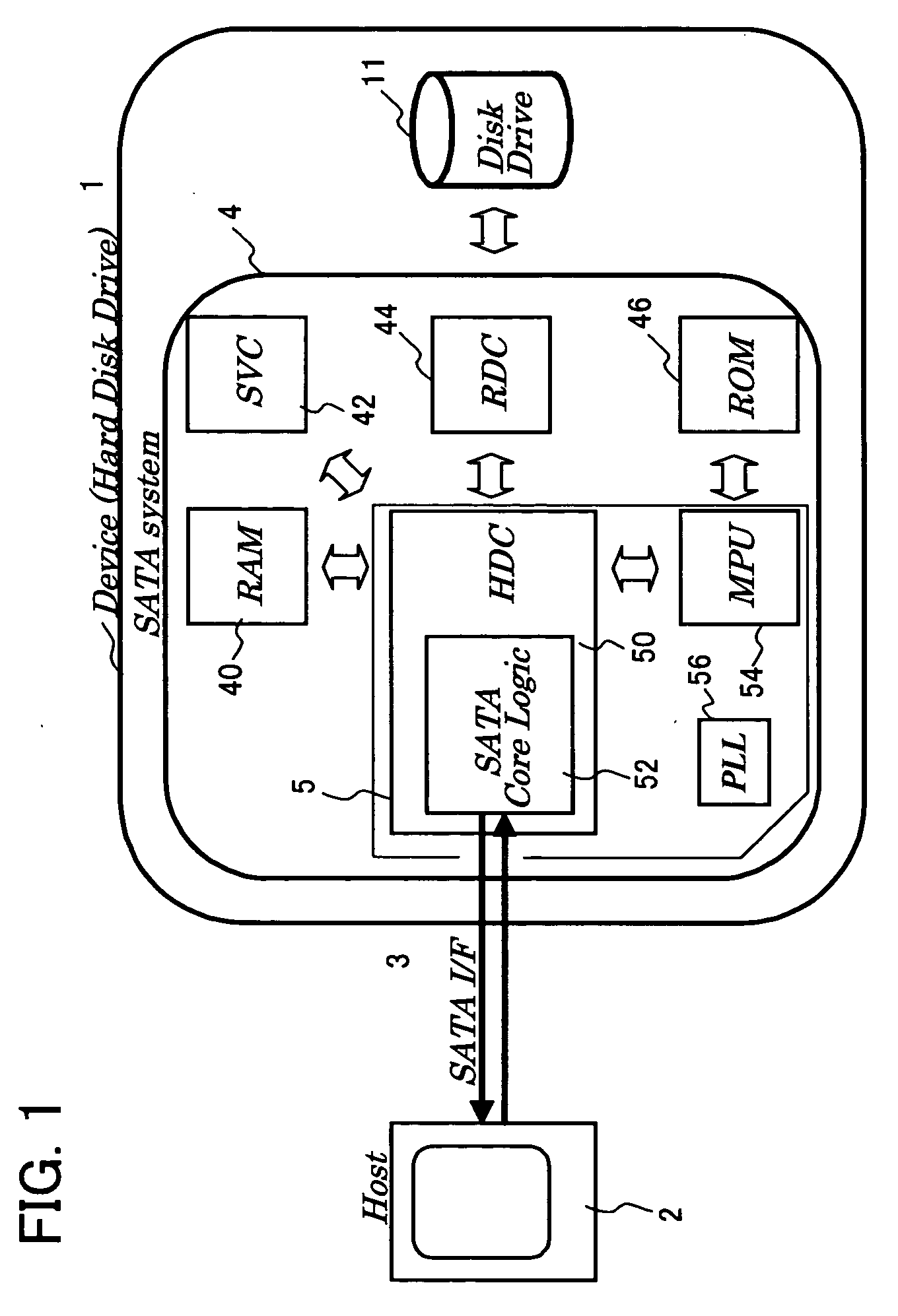
[0054]FIG. 1 is a block diagram depicting an embodiment of the serial interface type device of the present invention, and a hard disk drive is shown as an example of the device.

[0055] As FIG. 1 shows, the hard disk drive 1 is connected to the host (computer, such as an MPU) 2 via the SATA (Serial AT Attachment) interface 3. The hard disk drive 1 has a control block (SATA system) 4 and a disk drive mechanism 11. The disk drive mechanism 11 has a magnetic disk, a spindle motor for rotating the magnetic disk, an arm having a magnetic head, a VCM (Voice Coil Motor) for driving the arm and a read / write amplifier.

[0056] The SATA system 4 is for controlling the disk...


PUM


Abstract

A power saving of a serial interface circuit decreases the unnecessary power consumption of a serial interface circuit, while decreasing the return time and expanding the power saving range. Gates are disposed for stopping the clock supply to a digital portion of the interface circuit while maintaining operation of clock sources in the digital portions. Therefore a quick shift to and return from the power save mode by stopping and restarting clocks is implemented, which further decreases power consumption.

Description

CROSS-REFERENCE TO RELATED APPLICATIONS [0001] This application is based upon and claims the benefit of priority from the prior Japanese Patent Application No. 2004-022823, filed on Jan. 30, 2004, the entire contents of which are incorporated herein by reference. BACKGROUND OF THE INVENTION [0002] 1. Field of the Invention [0003] The present invention relates to a serial type interface circuit for decreasing the power consumption of an interface circuit and a device when data is transferred between a host and the device via a high-speed serial interface, a power saving method thereof, and a device having such a serial interface. [0004] 2. Description of the Related Art [0005] As the processing of microprocessors (MPU) improves, the improvement of the transfer speed between the host computer and a peripheral device (e.g. hard disk drive) is demanded. As such demand increases, a high-speed serial interface using a packet type protocol has been proposed. [0006] The parallel interface t...

Claims


Application Information

Patent Timeline
Patent Type & Authority Applications(United States)
IPC IPC(8): G06F1/32G06F1/04H04B1/38
CPCG06F1/3203G06F1/3237G06F1/325Y02B60/32Y02B60/1221Y02B60/1246G06F1/3268Y02D10/00Y02D30/50
Inventor MATSUMOTO, KAZUNARISUGAHARA, HIROHIDETAKEUCHI, KATSUHIKOUTSUNOMIYA, SHINICHIMATSUBAYASHI, SUMIEMYOUGA, NOBUYUKI
Owner KK TOSHIBA
Why Eureka
Try Eureka