Low power fingerprint capture system, apparatus, and method

a fingerprint capture and low-power technology, applied in the field of low-power fingerprint capture systems and apparatuses, can solve the problems of not teaching, the distance between the object plane and the image plane is too large to put the entire device into a physically compact solution, and the distance between the object plane and the image plane is too large to achieve the effect of efficient use, short focal distance, and increasing aberration

Active Publication Date: 2005-08-04
IDENTIFICATION INT
View PDF24 Cites 131 Cited by
  • Summary
  • Abstract
  • Description
  • Claims
  • Application Information

AI Technical Summary

Benefits of technology

[0047] In the present invention, depth of field issues in some embodiments do not drive the lens requirement so a shorter focal distance lens can be used at the expense of potentially increasing aberrations. But, since such aberrations are predictable, they can be reasonably corrected using software that implements the Ojanen algorithm. Another important side effect of a shorter focal length lens is the f-stop setting. Since a low depth of field is required, a lower f-stop lens is used so that more efficient use is made of the light and thus size and power requirements are further reduced.
[0048] The system power requirements of the present invention are reduced to the point that the device can be run within the limits of...

Problems solved by technology

Several patented systems do not teach that TIR be used at the fingerprint imaging surface in order for a fingerprint to be captured.
In the first case, if additional optical components are added, the size and weight of the device increase.
Long focal length lenses often result in a distance from the object plane to the image plane that is too large to put the entire device into a physically compact solution.
In addition, high f-stop lenses restrict the amount of light entering a camera and therefore more light, power, and/or exposure are needed for these systems, thus implying a larger power consumption.
Often aberrations in the periphery of the image such as barrel distortion and pincushion distortion distort the fingerprint to the point where the images are not truly usable.
Therefore, prior art large format fingerprin...

Method used


Image

  • Low power fingerprint capture system, apparatus, and method
  • Low power fingerprint capture system, apparatus, and method
  • Low power fingerprint capture system, apparatus, and method

Examples


first embodiment

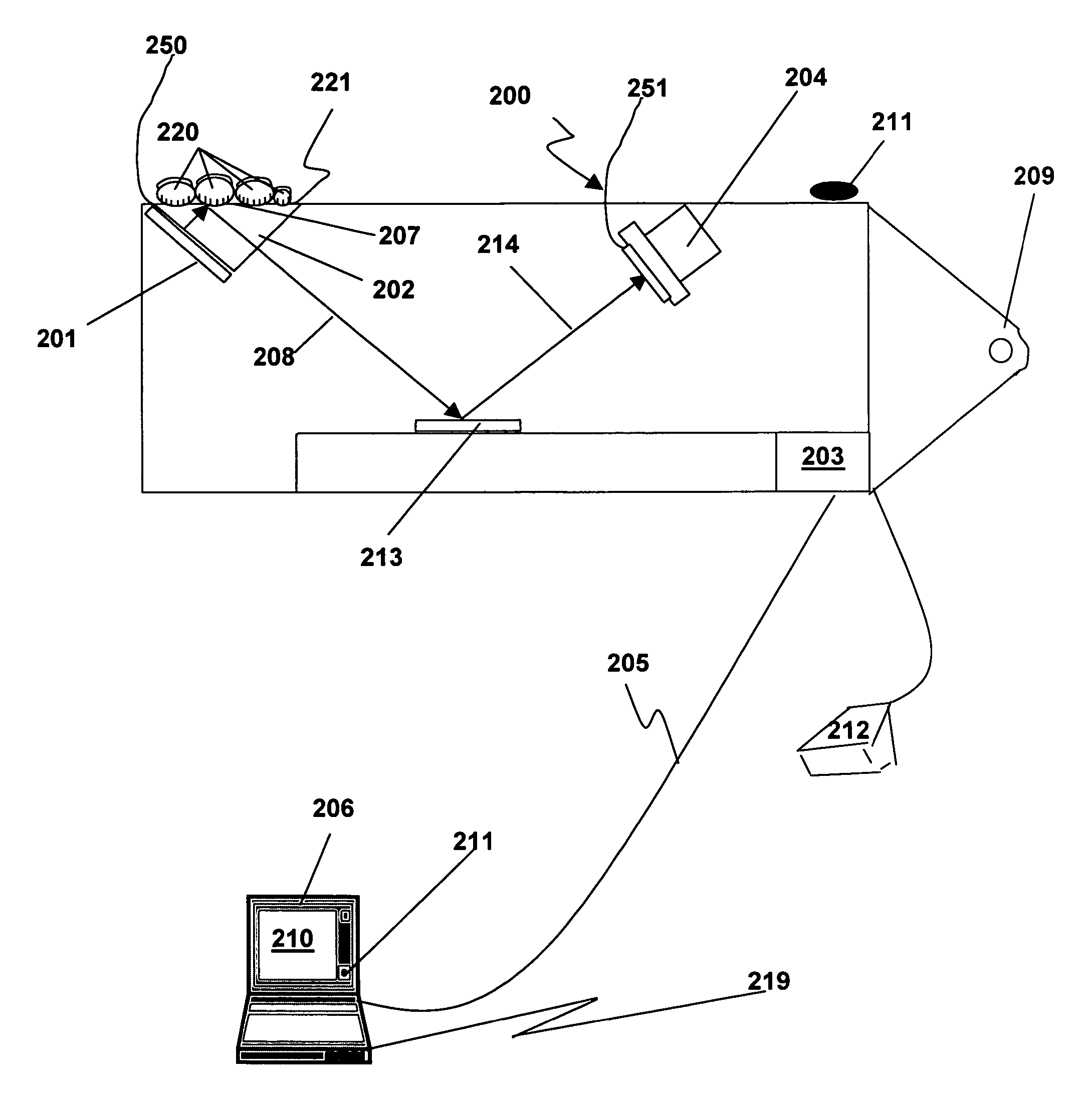
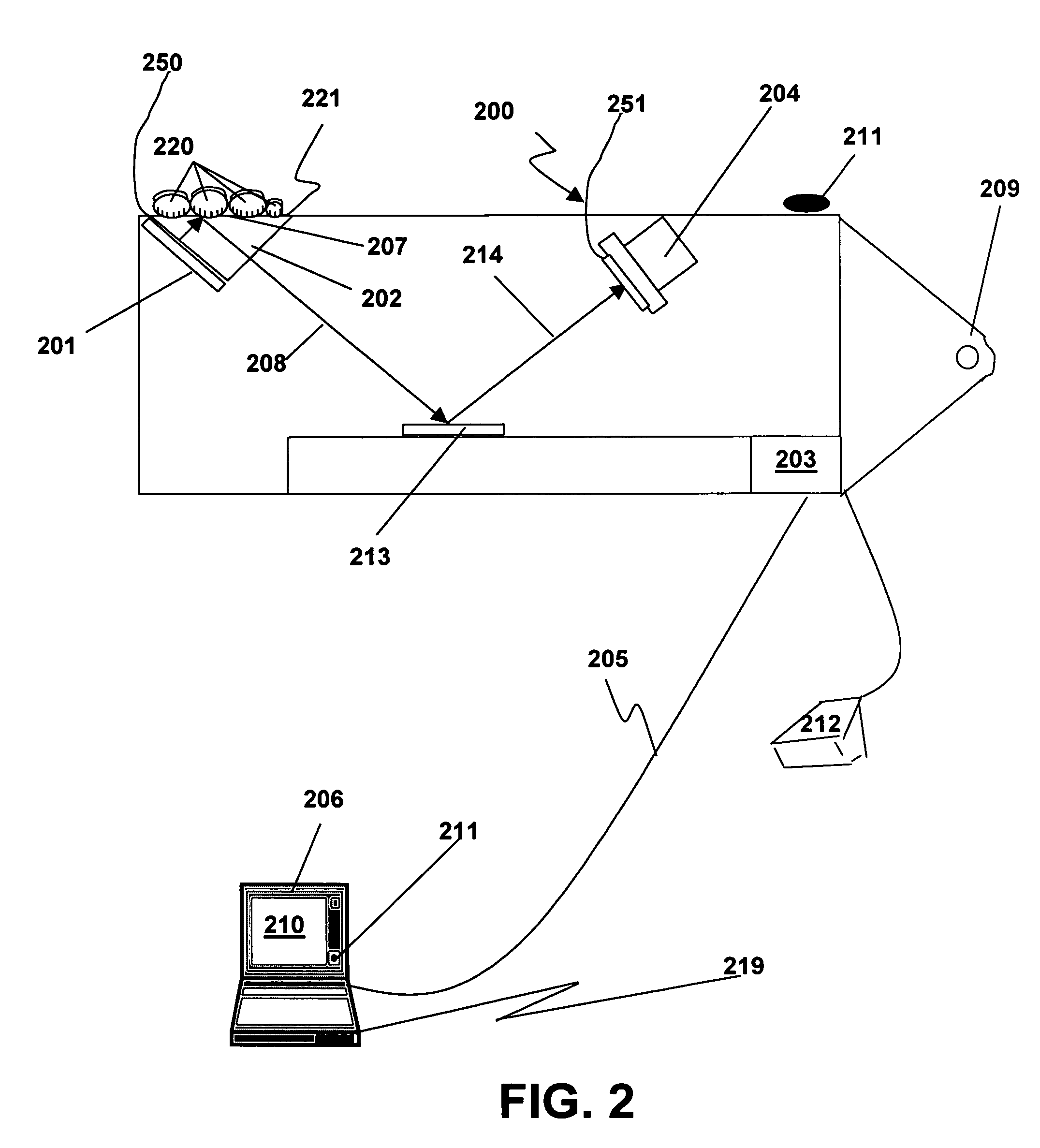
[0077] Referring now to FIG. 2, a first preferred embodiment of the present invention serves as a basic embodiment on which all other embodiments are founded. The first preferred embodiment has especially low power consumption, consuming at most between 3.0 and 10.0 watts, preferably at most about 2.5 watts, to lower battery drain on a host computer not connected to an electrical outlet.

[0078] As illustrated in FIG. 2, the first preferred embodiment includes a camera 204 having a lens and optionally a filter 251, an efficient light source 201 that consumes at most about 1 watt, preferably at most about 0.7 watt, and emits sufficient light for the camera 204 to obtain an acceptable image, a prism 202, an optional light control film 250 interposed between said light source 201 and said prism 202, and an interface 205 to a host computer 206. In this first preferred embodiment, light emitted by the efficient light source 201 enters the prism 202, is controlled by the light control film...

second embodiment

[0090] Referring now to FIGS. 3A-B, a second preferred embodiment of the present invention includes an efficient light source 201, a prism 202, a holographic grating 301 on an upper surface of the prism 202 and a light-transmitting substrate 302 on the holographic grating 301, a camera 204 having a lens, and an interface 205 to a host computer 206, and the host computer 206. The holographic grating 301, light transmitting substrate 302 and the upper surface 221 of the prism 202 together form a platen. Optionally, the holographic grating 301 is attached by an adhesive to the upper surface 221 of the prism 202 and to the lower surface of the light transmitting substrate 302 by an adhesive (not shown). Typically the holographic grating 301, light transmitting substrate 302 and the prism 202 are made of glass or acrylic polymer. In this second preferred embodiment, light emitted by the efficient light source 201 (light pipe) enters the prism 202 intersecting the prism surface 221 at an ...

third embodiment

[0093] The embodiment illustrated in FIG. 4 is substantially similar to that of FIG. 3B but shows a power subsystem 401 based upon a Lithium ion battery 402. In this subsystem, a Microsemi LX2201 chip, or similar chip, can be effectively used to provide power to the electrical consumers in the system. If enough power enters the system through the tether 205, this power is directed to the appropriate electronic components using a switching implementation driven by software and firmware resident on the device 400. Extra power not used by the devices is used to charge the battery 402 under the control of the software, firmware, or hardware.

[0094] In an alternative embodiment a capacitor 402 or a solar cell (not shown) replaces the Lithium ion battery 402. Such a construction can be used when a power shortage is temporary and can be served by the capacity of the capacitor being used.


PUM


Abstract

The present invention provides a large format fingerprint capture apparatus, system and method that is low power, compact, and lightweight and has a platen area greater than 3.0 square inches. The present system is typically powered, controlled, and exchanges data over a single data/control/power connection to a host PC, e.g., a desk top computer, PDA, or laptop computer although the system can also be used in a wireless fashion with a power subsystem so no physical connections are required. In a preferred embodiment the large format fingerprint device is directly connected to a completely disconnected portable PC, such as a laptop having only a battery power source. The primary system components of the present invention combine to minimize power, size and weight and, thus, enhance portability and battery life. The system typically includes a light source, a prism, a camera (including the lens), and a case. Optional elements comprise holographic elements such as gratings and holographic optical elements (HOEs), a battery subsystem, magnetic stripe reader, barcode reader, platen heater, platen blower, and mirrors to divert the image beam.

Description

CROSS REFERENCE TO RELATED APPLICATION [0001] This is a non-provisional application claiming the benefit under 35 U.S.C. 119 of provisional application No. 60 / 534,394 filed on Jan. 7, 2004, the entire disclosure of which is hereby incorporated by reference.BACKGROUND OF THE INVENTION [0002] 1. Field of the Invention [0003] The present invention relates to a system, apparatus, and method for the collection of friction ridge signatures from a subject. More particularly, the present invention relates to a low power consumption, small size, and low weight friction ridge capturing device and method for the collection of friction ridge signatures from a subject. Most particularly, the present invention relates to a low power consumption, compact, and portable digital friction ridge capturing apparatus, system and method for the collection of friction ridge signatures with a platen area of at least 3.0 square inches. [0004] 2. Description of the Related Art [0005] Human beings have frictio...

Claims


Application Information

Patent Timeline
IPC IPC(8): G06K9/00
CPCG06K9/00046G06K9/00026G06V40/1324G06V40/1335G06V40/1359
Inventor FENRICH, RICHARDSALERNO, NICHOLASHUTCHINS, JEREMYPEDIGO, MICHAELGAEBE, CARL
Owner IDENTIFICATION INT
Why Eureka
Try Eureka