Turbochargers

a turbocharger and turbocharger technology, applied in the field of turbochargers, can solve the problems of restricted interfacial connection and turbocharger failure, and achieve the effects of reducing thermal expansion coefficient, greater strength, and greater strength

Active Publication Date: 2005-08-04
WABTEC UK LTD
View PDF3 Cites 38 Cited by
  • Summary
  • Abstract
  • Description
  • Claims
  • Application Information

AI Technical Summary

Benefits of technology

[0006] According to the invention, there is provided a turbocharger having an impeller, the impeller being formed of a first material and being mounted on a turbocharger shaft by means of an insert that is an interference fit in the impeller, the insert comprising a second material of greater strength than the first material, and a constraining ring comprising a material having greater strength and a lower coefficient of thermal expansion than the first material, the constraining ring surrounding at least a part of an axial length of the impeller that overlies the insert, thereby to maintain the interference between the insert and the impeller during use of the turbocharger over its operating speed and temperature range.

Problems solved by technology

The resultant interference connection is restricted by the temperature to which the aluminum can be heated before its material properties are affected, and by the temperature to which the steel can be cooled.
While the arrangement described can perform satisfactorily, a problem can arise during cycling of the turbocharger from rest to full load.
In certain very cyclic conditions (for example fast ferry applications in high ambient temperatures), it has been observed that the insert can move so far along the impeller that turbocharger failure can occur.
Although the effect can be mitigated to some degree by increasing the original interference between the components, for the reasons mentioned above this solution is limited, and it is therefore desirable to achieve a design which ensures that the point of grip remains at the same location during the operating cycles, rather than shifting from one end of the insert to the other.

Method used


Image

  • Turbochargers
  • Turbochargers
  • Turbochargers

Examples


Embodiment Construction

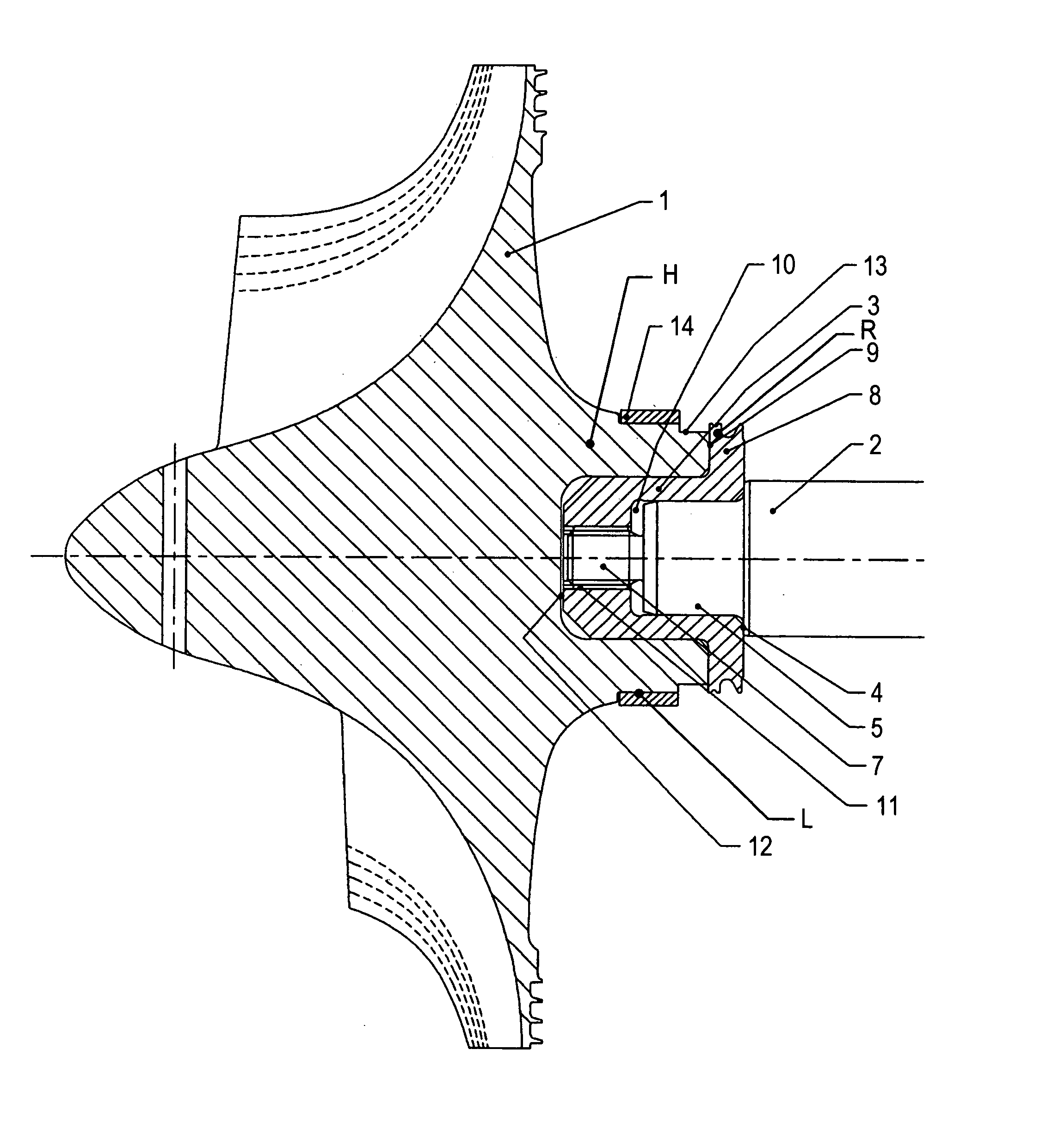
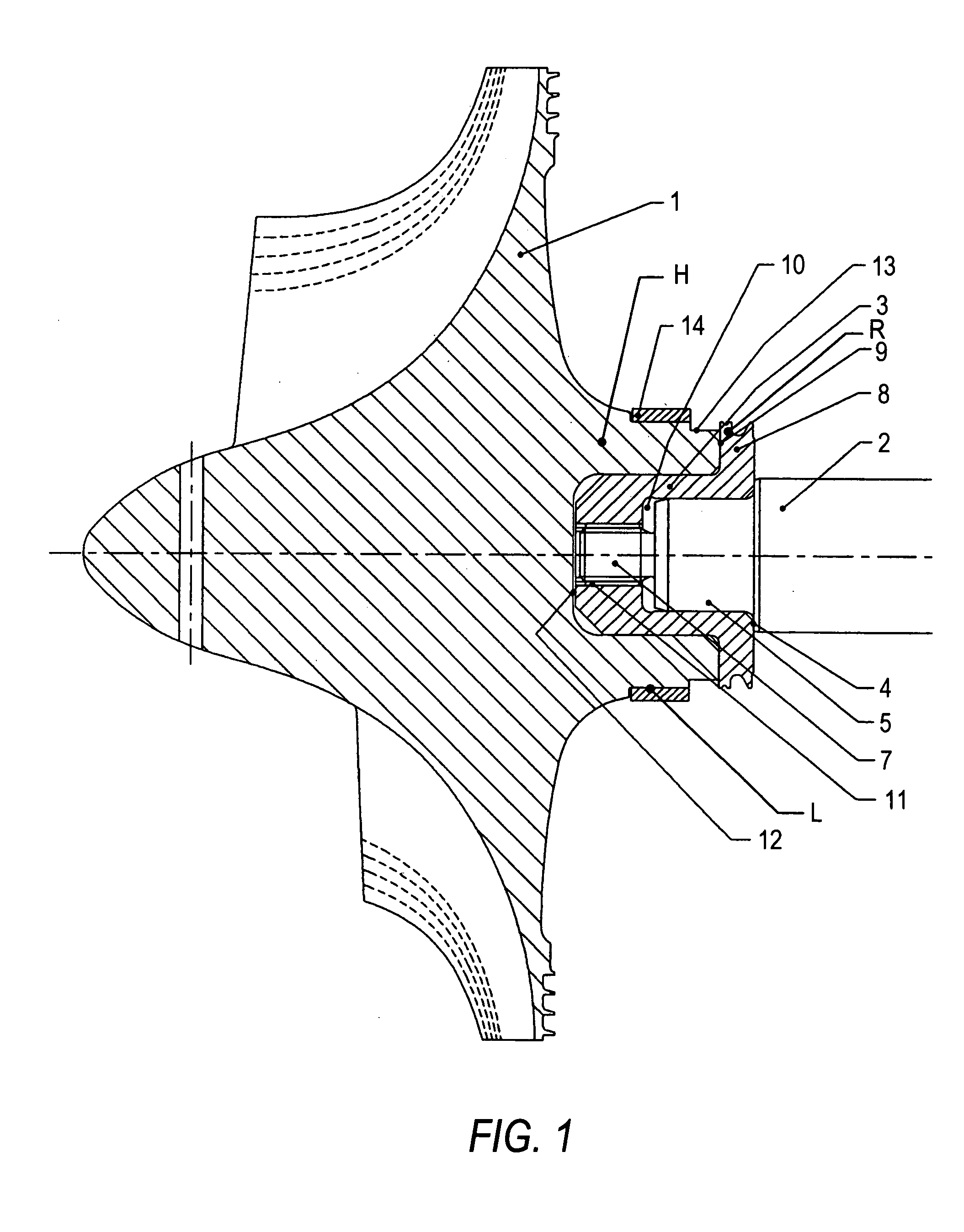
[0016] Referring first to FIG. 1, an aluminum alloy impeller 1 is fitted onto a steel turbocharger shaft 2 by means of a steel insert 3. The alloy of which the impeller is made (known in the United States by the designation “2618A”) has a relatively high strength for use up to a temperature of about 200 degrees Celsius, having a composition of aluminum with about 2.5 wt. % copper and smaller amounts of magnesium, iron and nickel. The insert 3 may be made of a free-machining mild steel and is located in the central hub H of the body of impeller 1.

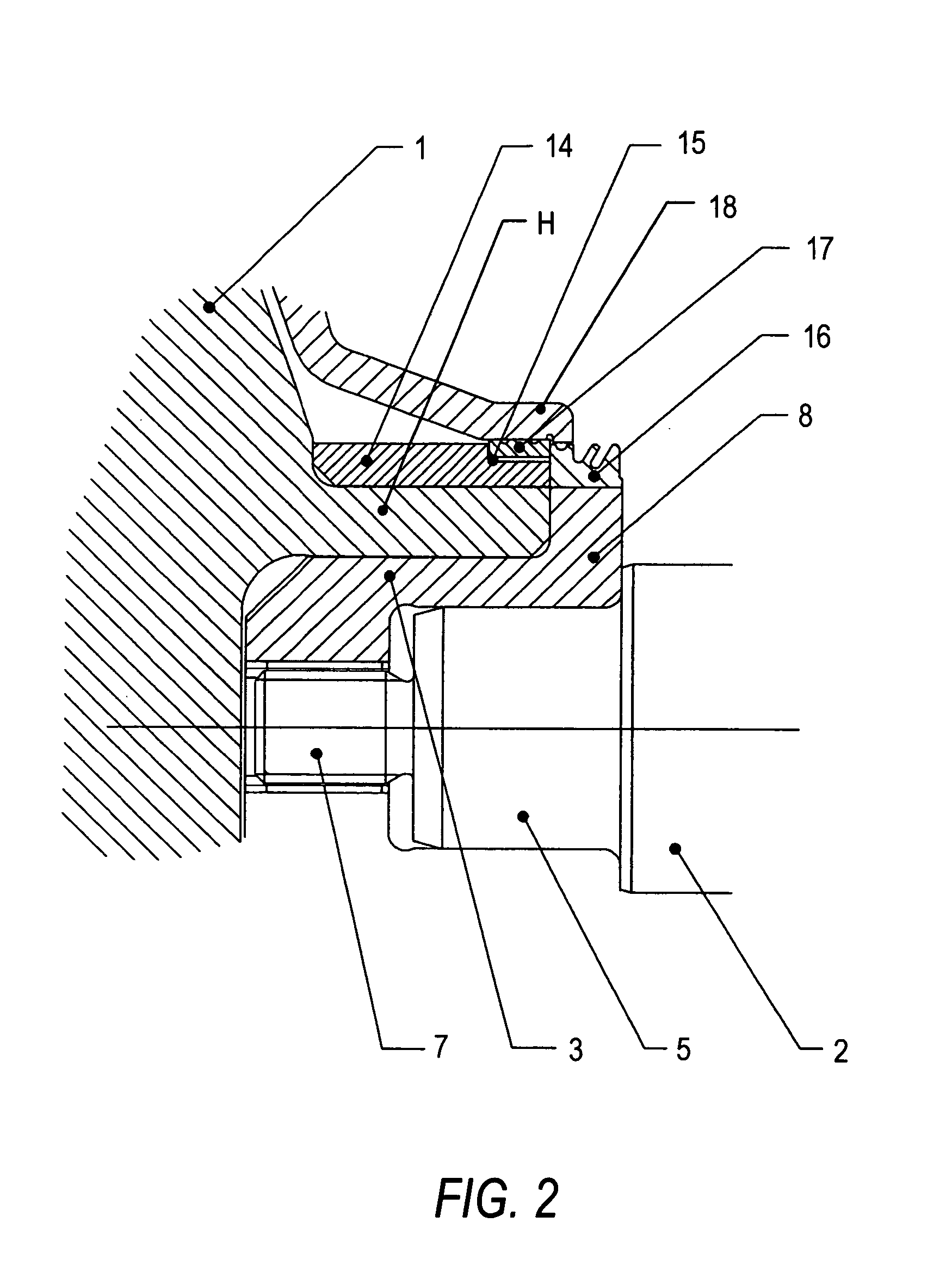
[0017] The shaft 2 is formed at its end with a first shoulder 4 surrounding a cylindrical locating portion 5, and a screw-threaded portion 7 of further reduced diameter extending from the end of the locating portion. The steel insert 3 is of generally cup-like shape, having a flange 8 around its mouth engaging against the end face 9 of the impeller hub H and in turn being engaged on its other side by the shoulder 4 on the shaft 2. The locat...


PUM


Abstract

A turbocharger has a shaft formed of a strong material such as steel and an impeller formed of a relatively weaker material such as aluminum alloy. The impeller is mounted on the shaft by means of an internally-threaded insert, for example also of steel, interference fitted into the impeller hub. To prevent loss of the interference fit between the insert and impeller during thermal and speed excursions of the impeller during operation of the turbocharger, a constraining ring is fitted to the hub of the impeller. The ring is of a material having a lower coefficient of thermal expansion than the material of the impeller and surrounds at least a part of that axial length of the impeller which overlies the insert.

Description

FIELD OF THE INVENTION [0001] This invention relates to turbochargers and to impellers for turbochargers. BACKGROUND TO THE INVENTION [0002] Turbocharger impellers are typically made of aluminum alloys to provide low rotational inertia with reasonable strength at a commercially acceptable cost. Attachment of the impeller to the steel turbocharger shaft is achieved in various ways, but because of the relative weakness of aluminum and the small diameter of the shaft, it is desirable to provide the impeller with a steel insert containing a screw-threaded socket which can be threaded onto the shaft. This arrangement can take a higher torque than a connection in which the shaft is directly threaded into the aluminum body (the torque is proportional to the power transmitted across the joint, and so the impeller can be used at a higher pressure ratio than one in which there is a direct threaded connection). [0003] Typically, such an insert is fitted into the impeller by shrink fitting; the...

Claims


Application Information

Patent Timeline
Patent Type & Authority Applications(United States)
IPC IPC(8): F01D5/02F01D5/04F01D25/00F02C6/12F04D29/26F04D29/28
CPCF01D5/025F01D5/048F01D25/005F02C6/12F05D2300/50212F04D29/284F05D2240/70F05D2220/40F05D2260/30F04D29/266
Inventor GEOFFREY HEYES, FRANCIS JOSEPHBROWN, IAN PATRICK CLARE
Owner WABTEC UK LTD
Why Eureka
Try Eureka