Check patentability & draft patents in minutes with Patsnap Eureka AI!

Capillary pins for high-efficiency microarray printing device

a printing device and high-efficiency technology, applied in the direction of positive displacement liquid engines, laboratory glassware, instruments, etc., can solve the problems of inability to accurately synthesize molecules, inability to accurately identify the sequence of the array, and the efficiency of each synthetic step affecting the quality and integrity of the array, etc., to achieve the effect of improving reagent usage and small feature size and spacing

Inactive Publication Date: 2005-08-04
RGT UNIV OF CALIFORNIA
View PDF55 Cites 20 Cited by
  • Summary
  • Abstract
  • Description
  • Claims
  • Application Information

AI Technical Summary

Benefits of technology

The present invention provides improved components and microarray printing devices for high-density array printing. The invention allows for smaller feature sizes and better reagent usage. The invention includes a microarray print head with improved spotting capillaries that can move in a direction parallel to the long axis of the capillaries and have a fixed spacing between them. The print head can also have a vacuum chamber to hold the capillaries and a port to apply vacuum. The invention also provides a microarray substrate holder with vacuum ports and a spring-loaded retainer for positioning each substrate. Overall, the invention allows for faster and more efficient printing with microarrays.

Problems solved by technology

Each approach has its own limitations and drawbacks.
For example, when an array is created by direct synthesis onto an array support, the efficiency of each synthetic step affects the quality and integrity of molecules forming the array.
The magnitude of the problem increases with the complexity of the individual molecules, potentially resulting in an undesirable percentage of incorrectly synthesized molecules and incomplete sequences.
Such contaminants can interfere with subsequent use of the array.
(U.S. Pat. No. 5,384,261), are generally unable to construct microarrays of large macromolecules.
Such technologies can also be expensive and difficult to implement.
Inkjet devices require high reagent volumes and risk “probe” degradation during volatilization.
Direct surface contact printing (see, e.g., U.S. Pat. Nos. 4,981,783, 5,525,464, 5,770,151, and 5,807,522), are limited in their ability to reliably, reproducibly, and uniformly apply the array elements to the array substrate.
Reagent usage is also relatively inefficient, and array density is limited.

Method used


Image

  • Capillary pins for high-efficiency microarray printing device
  • Capillary pins for high-efficiency microarray printing device
  • Capillary pins for high-efficiency microarray printing device

Examples


Embodiment Construction

[0054] This invention pertains to a microarray printer that can be used to manufacture microarrays (e.g. of biochemical samples) by direct contact printing. The array printer of this invention is capable of printing microarrays at higher feature density, with greater speed and lower cost than previous microarray printing devices.

[0055] Without being bound to a particular theory, these efficiencies are achieved by the use of a combination of novel features. A novel printing pin permits vastly more efficient reagent usage and a greater number features to be printed per load. This reduces reagent costs, and because the pin does not require repeated refills during the printing process, the printing operation proceeds more rapidly.

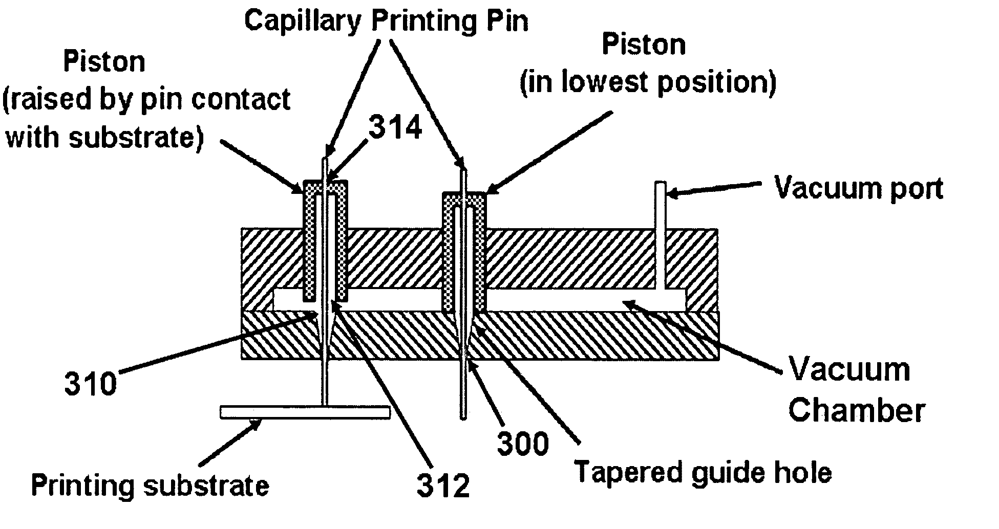
[0056] In addition, positive control of reagent flow using pressure and vacuum, also improves reagent capture and delivery and reduces the incidents of mis-prints due to pin blockage during loads or print steps. In addition, positive pressure control keeps th...


PUM

PropertyMeasurementUnit
load volumeaaaaaaaaaa
volumeaaaaaaaaaa

Abstract

This invention provides improved components (e.g. array “pins”, print head, substrate platen, print head platen, and the like) for microarray printing devices as well as microarray printing devices incorporating such components. In one embodiment, this invention provides a microarray print head comprising a plurality of glass or quartz spotting capillaries disposed in a support that maintains a fixed spacing between the spotting capillaries and that permits the spotting capillaries to move in a direction parallel to the long axis of the capillaries.

Description

CROSS-REFERENCE TO RELATED APPLICATIONS [0001] This application is a continuation-in-part of continuation of Ser. No. 10 / 456,943, filed Jun. 6, 2003 and PCT / US02 / 20766, filed Jun. 27, 2005 both of which are continuations-in-part of U.S. Ser. No. 09 / 894,863, filed on Jun. 27, 2001, all of which are incorporated herein by reference in their entirety for all purposes.STATEMENT AS TO RIGHTS TO INVENTIONS MADE UNDER FEDERALLY SPONSORED RESEARCH AND DEVELOPMENT [0002] [Not Applicable]FIELD OF THE INVENTION [0003] This invention pertains to the field of high-density microarray production. In particular, this invention provides methods and devices that permit high-density arrays to be printed with significantly smaller feature size and spacing and greatly improved reagent usage. BACKGROUND OF THE INVENTION [0004] The immobilization of test molecules or “probes” on array supports has had a significant impact on drug discovery, medical diagnostic methods, and basic research. The use of high-d...

Claims


Application Information

Patent Timeline
Patent Type & Authority Applications(United States)
IPC IPC(8): B41J2/005B41J2/25C12Q1/68
CPCB41J2/005B41J2/25C12Q1/6837C12Q2565/507
Inventor PINKEL, DANIELALBERTSON, DONNA G.HAMILTON, GREGBROWN, NILS W.NORDMEYER, ROBERT
Owner RGT UNIV OF CALIFORNIA
Features
  • R&D
  • Intellectual Property
  • Life Sciences
  • Materials
  • Tech Scout
  • Unparalleled Data Quality
  • Higher Quality Content
  • 60% Fewer Hallucinations
Learn More