Membrane and a method of producing a membrane

a technology of membranes and membranes, applied in the field of membranes and a production method, to achieve the effect of high impact resistance and low frictional properties

Inactive Publication Date: 2005-08-04
ICOPAL PLASTIC MEMBRANES
View PDF9 Cites 52 Cited by
  • Summary
  • Abstract
  • Description
  • Claims
  • Application Information

AI Technical Summary

Benefits of technology

[0014] It is an advantage of the present invention that the technique according to the present invention of producing edge reinforced scaffold membranes may be easily established by a simple modification of the prior art technique of producing fabric, grid, mesh or scrim reinforced membranes according to the technique described in applicant's above mentioned international patent application.
[0020] interlaying and sandwiching the reinforcing fabric, grid, mesh or scrim between the first and second foils and positioning the bands edgewise at the first and second foils, and at least partly overlapping the reinforcing fabric, grid, mesh or scrim, and laminating the first and second foils together and to the bands for sandwiching foils within the sandwich structure and for providing an integral structure in which the bands are laminated integrally to one of the foils or both the foils, and at least partly overlapping the reinforcing fabric, grid, mesh or scrim.
[0027] the bands being positioned edgewise at the first and second foils, and providing an integral structure in which the bands are laminated integrally to one of the foils or both of the foils, and at least partly overlapping the reinforcing fabric, grid, mesh or scrim.
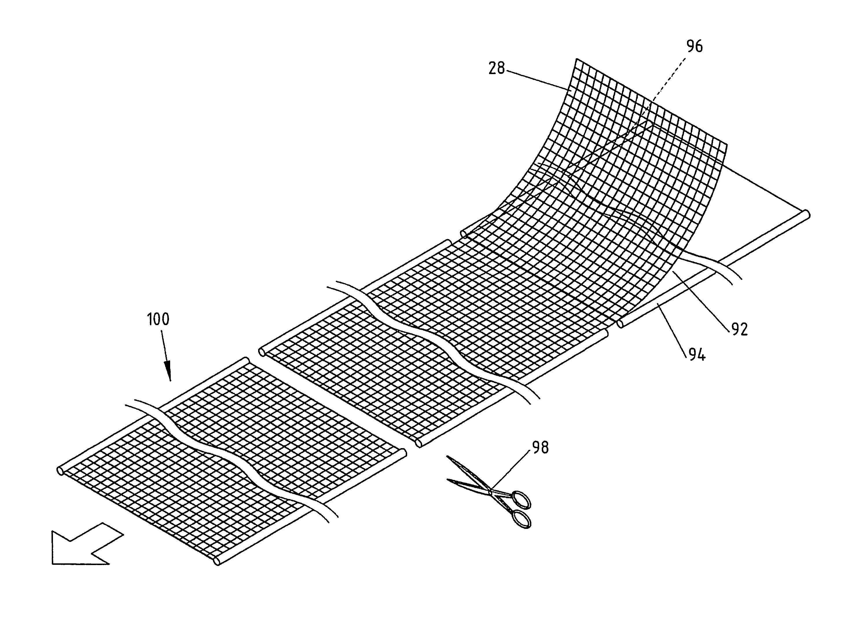
[0028] It is an advantageous feature of the present invention, that two bands of polymer materials, preferably weather resistant polymer materials exhibiting fairly low frictional properties are laminated between the two foils of the composite foil assembly or to the one side being the top surface or the bottom surface of the composite foil assembly by utilizing the facility of the production process of producing the composite fabric, grid, mesh or scrim reinforced membrane for integrally producing the edge reinforcing band as an integral part of the membrane structure. Furthermore, according to an essential feature of the present invention, the two bands of polymer materials which are laminated to the sandwiched structure or into the sandwiched structure through one of the foils or alternatively between the two foils, respectively, are positioned so as to establish an overlap between said bands and said reinforcing fabric, grid, mesh or scrim.
[0029] It is to be realized that the membranes produced according to the present invention are intended to be used as scaffold sheeting or used for similar application in which the membrane may be exposed to even extreme weather conditions including rough wind or storm and heavy rain or snow. Consequently, in a scaffold covering structure in which the membranes are mounted by means of ‘Keder’ strings included in the edge reinforcing bands characteristic of the present invention, the overall structure including the junction between the edge reinforcing bands and the composite foil assembly have to allow the structure to have high impact resistance.
[0030] In the present context, the following terms: Fabric, grid, mesh or scrim are to be construed comprising any fiber, filament, tape or wire structure of plastics material or any other relevant material, such as e.g. carbon reinforced plastic material etc. which exhibits an overall geometrical configuration resembling a fabric, grid, mesh or scrim or any other structure differing from a conventional fabric, grid, mesh or scrim, still fulfilling the same purpose as a reinforcing fabric, grid, mesh or scrim. In the below description, it is stated that the fabric, grid, mesh or scrim may have any appropriate configuration and also have varying dimensions and all embodiments complying with the above definition are consequently to be considered covered by the term fabric, grid, mesh or scrim.

Problems solved by technology

Consequently, the membranes have to comply with certain requirements as to strength, as defined in relevant ISO, BS, EN or DIN standards and have additionally to fulfill certain additional characteristics, which are often difficult to measure or specifically determine, which characteristics are, however, within the industry, often referred to as toughness, crack resistance, abrasive resistance, draping and noise characteristics.
However, the punctures in the fabric that result from the sewing may cause water ingress and heat-sealing of the fabric may be used to form the pockets for providing a stronger seam with no punctures to weaken the fabric at the seam.

Method used


Image

  • Membrane and a method of producing a membrane
  • Membrane and a method of producing a membrane
  • Membrane and a method of producing a membrane

Examples


example 1

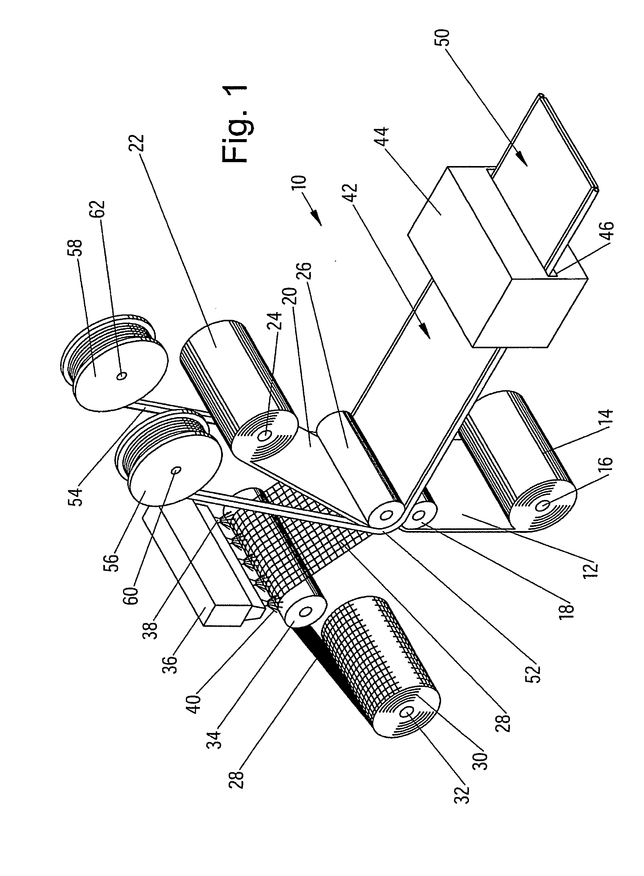
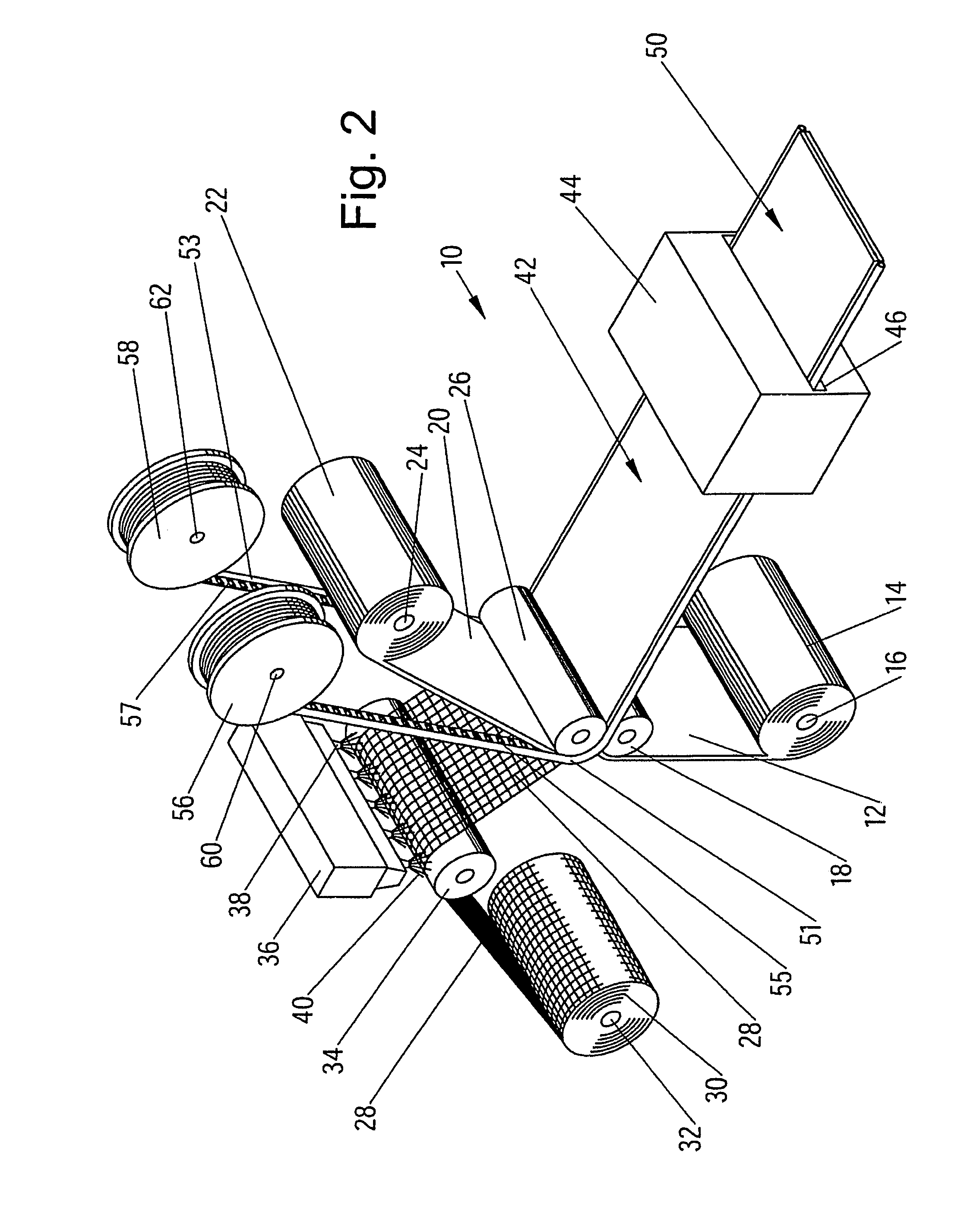
[0136] By means of the process line shown in FIG. 3, a continuous composite membrane was made from the following components: The foil 12 was an 80 μm LDPE foil including flame retardants. The mesh 28 was an 8×8 mm mesh size PET mesh of 1670 dtex multifilament yarn. The top foil or coating layer 25 was a 120 μm LDPE foil including flame retardants. The ‘Keder’ bands 52 and 54 were constituted by 200 mm width HDPE woven bands applied to the top surface of the coating layer or top foil 25. In an additional process step similar to the process illustrated in FIG. 7, the 200 mm HDPE woven bands were turned over and were adhered to the respective band enclosing an 8 mm plasticized PVC ‘Keder’ string. The width of the composite membrane was 2.57 m, and in the alternative variant, the width was 3.0 m.

example 2

[0137] In an alternative embodiment, a pre-fabricated ‘Keder’ web made from woven PE fabric and including a 8.5 mm plasticized PVC string is laminated to the top foil or coating layer 25 in the process illustrated in FIG. 3 while employing the roller 26′ shown in FIG. 17 and the foil 12, the mesh 28 and the top foil or coating layer 25 as specified in Example 1 above.

example 3

[0138] In the process line shown in FIG. 4, the foil 12 is constituted by a 250 μm PE foil including frame retardants, the mesh 28 is the mesh of Example 1 above without lubrication and the top foil or coating layer 25 is a 250 μm PE foil.

[0139] The ‘Keder’ bands 52 and 54 are constituted by woven PE bands of a width of 100 mm having apertures measuring 20×25 mm. Like the above described Example 1, a ‘Keder’ string of plasticized PVC of a diameter of 8.5 mm is used.

[0140] Apart from the below claims, the following points are also relevant in defining the present invention:

[0141] Point 1. The method according to any of the below claims 1-15, said polymer material of said first and / or said second foil being PE, preferably LDPE or MDPE; LLDPE; VLDPE, alternatively termed plastomers; EVA; EBA; EMA; EAA; PP, preferably isotactic polypropylene homopolymer; random copolymers of propylene and ethylene, alternatively termed raco-PP; copolymers of propylene, ethylene and optionally higher ...


PUM


Abstract

A membrane, particularly a weather protection membrane, is made from a reinforcing element, such as a regularly laid, woven or non-woven fabric, grid, mesh or scrim having a dimensionally mechanical stable polymer fiber, filament or wire material. First and second polymer foils are provided, preferably of a weather resistant polymer material. Two bands of polymer material are further provided, preferably of a weather resistant polymer material, including a woven or non-woven layer and exhibiting low frictional properties. The reinforcing element is interlaid and sandwiched between the first and second foils, and the bands are positioned edgewise at the first and second foils, and at least partly overlapping the reinforcing element. The first and second foils are laminated together and to the bands for sandwiching the foils for providing an integral structure.

Description

CROSS-REFERENCE TO RELATED APPLICATION [0001] Not Applicable FEDERALLY-SPONSORED RESERAHC OR DEVELOPMENT [0002] Not Applicable BACKGROUND OF THE INVENTION [0003] The present invention relates generally to the technical field of membranes and a method of producing membranes, in particular weather protection membranes. The present invention relates in particular to a method of producing membranes for use in the field of house building or construction and integrally including edge reinforcing bands such as ‘Keder’ bands for fixating the membranes to supporting structures such as scaffolds, etc. The membranes may be used as a scaffold sheeting, a temporary roof cover, an underroof membrane, tarpaulins, geo membranes, world aid shelters, military shelters, green house or agricultural membranes, festival or leisure tents, etc. The present invention also relates to the membrane, in particular a weather protection membrane. [0004] Within the technical field of membranes, in particular membr...

Claims


Application Information

Patent Timeline
Patent Type & Authority Applications(United States)
IPC IPC(8): A01G9/14B32B3/06B32B3/08B32B27/12E04D12/00
CPCA01G9/1438B32B3/06E04D12/002B32B27/12B32B3/08Y10T442/10Y10T442/14Y10T442/145Y02A40/25B32B5/024B32B5/022B32B2419/06
Inventor CHRISTIANSEN, KIM K.MARCHER, BJORNGROTE, BETTINA
Owner ICOPAL PLASTIC MEMBRANES
Why Eureka
Try Eureka