
Ablation probe for delivering fluid through porous structure

a technology of porous structure and electrosurgical probe, which is applied in the direction of contraceptives, ceramicware, cell components, etc., can solve the problems of clogging of pores, and achieve the effect of increasing the number of pores

Active Publication Date: 2005-08-04
BOVIE MEDICAL CORPORATION
View PDF41 Cites 61 Cited by
  • Summary
  • Abstract
  • Description
  • Claims
  • Application Information

AI Technical Summary

Benefits of technology

[0009] The ablation probe further comprises a porous structure that is associated with the distal end of the shaft in fluid communication with the lumen. For example, the distal end of the shaft, or the entirety of the shaft, can be composed of the porous structure. Or, if the ablative element is an electrode, the electrode can be composed of the porous structure. In this case, the porous structure is preferably composed of an electrically conductive material, such as stainless steel, so that it is capable of conveying radio frequency (RF) energy. In this manner, an fluid can be conveyed through the lumen, and out through the porous structure into adjacent tissue during the ablation process. In the case where the ablative element is a single needle electrode, the needle electrode can be close ended, since perfusion of the fluid will occur through the porous structure. In general, a close ended needle electrode can penetrate through tissue more accurately. Because the pores within the porous structure are pervasive, the fluid will freely flow out into the tissue notwithstanding that some of the pores may become clogged. The porous structure may be macroporous or microporous, but in one preferred embodiment, the effective diameter of the pores will fall within the range of 1-50 microns.
[0011] In accordance with a first aspect of the present invention, the porous structure has a porosity in the range of 20-80 percent, preferably within the range of 30-70 percent. In this manner, structural integrity of the shaft and / or ablative element(s) can be maintained, while providing a free flow of fluid through the many channels within the porous structure. In accordance with a second aspect of the present invention, the porous structure is microporous in order to increase the number of pores that will perfuse the fluid. In accordance with a third aspect of the present invention, the porous structure may have interconnecting pores that are arranged in a random manner, in order to provide a more efficient flow of fluid through the porous structure.

Problems solved by technology

Because the pores within the porous structure are pervasive, the fluid will freely flow out into the tissue notwithstanding that some of the pores may become clogged.

Method used


Image

  • Ablation probe for delivering fluid through porous structure
  • Ablation probe for delivering fluid through porous structure
  • Ablation probe for delivering fluid through porous structure

Examples


Embodiment Construction

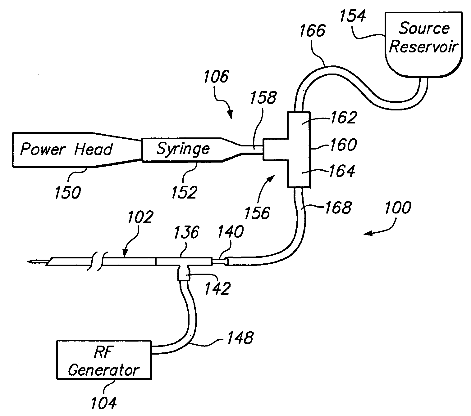
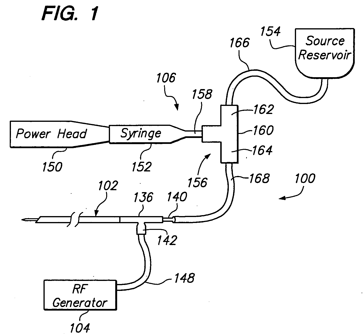
[0024]FIG. 1 illustrates a tissue ablation system 100 constructed in accordance with a preferred embodiment of the present inventions. The tissue ablation system 100 generally comprises a probe assembly 102 configured for introduction into the body of a patient for ablative treatment of target tissue; a radio frequency (RF) generator 104 configured for supplying RF energy to the probe assembly 102 in a controlled manner; and a pump assembly 106 configured for perfusing fluid, such as saline, out through the probe assembly 102, so that a more efficient and effective ablation treatment is effected.

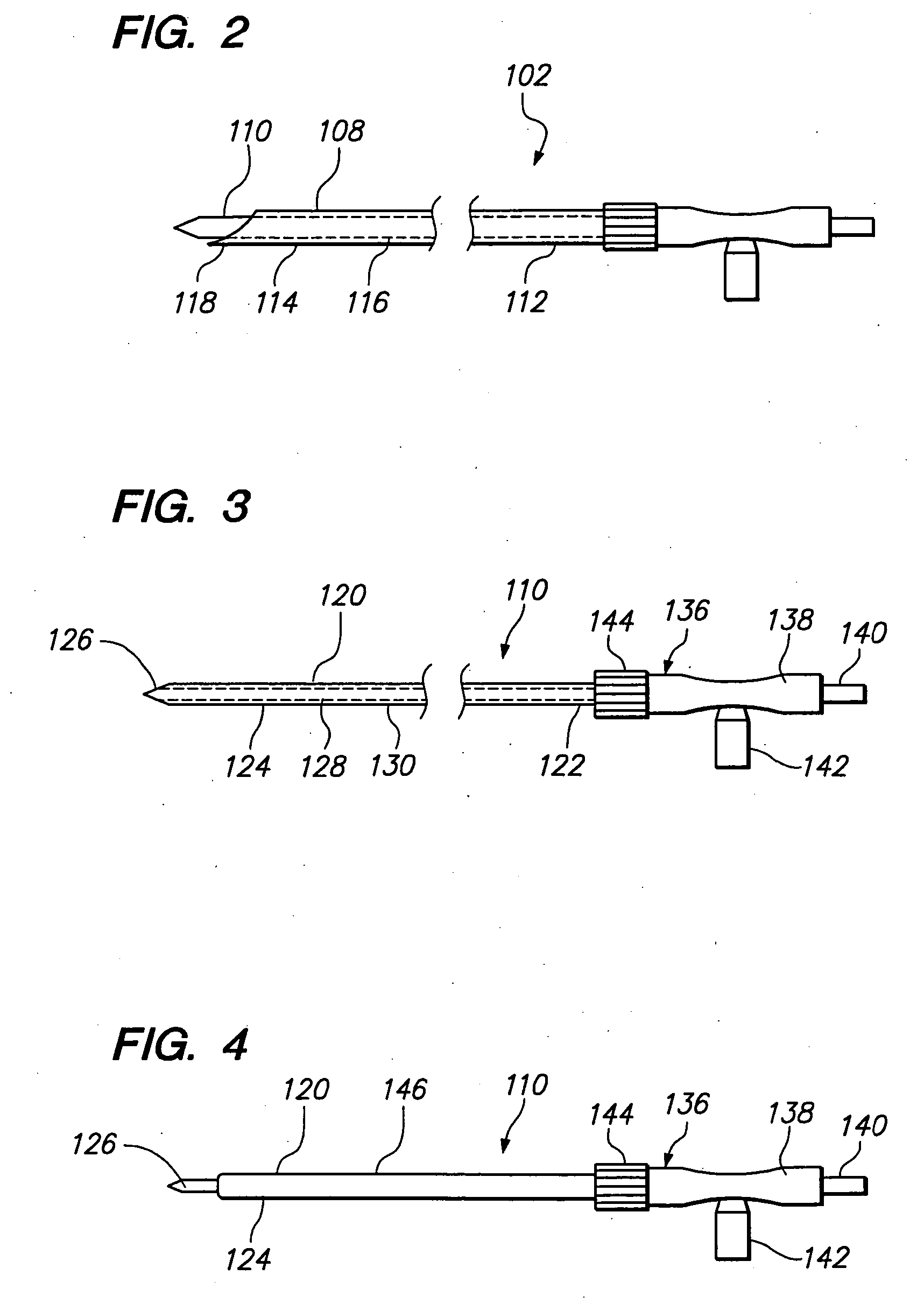
[0025] Referring specifically now to FIG. 2, the probe assembly 102 generally comprises an ablation probe 110 and a cannula 108 through which the ablation probe 110 can be introduced. As will be described in further detail below, the cannula 108 serves to deliver the active portion of the ablation probe 110 to the target tissue. The cannula 108 has a proximal end 112, a distal end 114, and ...


PUM

PropertyMeasurementUnit
Diameteraaaaaaaaaa
Porosityaaaaaaaaaa
Porosityaaaaaaaaaa

Abstract

Ablation probes are provided for perfusing the tissue, while the tissue is ablated. The ablation probe comprises an elongated shaft and an ablative element, such as a needle electrode. The ablation probe further comprises a lumen that extends through the probe shaft, which will be used to deliver an fluid to the distal end of the probe shaft for perfusion into the surrounding tissue. The ablation probe further comprises a porous structure that is associated with the distal end of the shaft in fluid communication with the lumen. For example, the distal end of the shaft, or the entirety of the shaft, can be composed of the porous structure. Or, if the ablative element is an electrode, the electrode can be composed of the porous structure. Because the pores within the porous structure are pervasive, the fluid will freely flow out into the tissue notwithstanding that some of the pores may become clogged.

Description

FIELD OF THE INVENTION [0001] The field of the invention relates generally to the structure and use of radio frequency (RF) electrosurgical probes for the treatment of tissue. BACKGROUND OF THE INVENTION [0002] The delivery of radio frequency (RF) energy to target regions within solid tissue is known for a variety of purposes of particular interest to the present invention. In one particular application, RF energy may be delivered to diseased regions (e.g., tumors) for the purpose of ablating predictable volumes of tissue with minimal patient trauma. RF ablation of tumors is currently performed using one of two core technologies. [0003] The first technology uses a single needle electrode, which when attached to a RF generator, emits RF energy from the exposed, uninsulated portion of the electrode. This energy translates into ion agitation, which is converted into heat and induces cellular death via coagulation necrosis. In theory, RF ablation can be used to sculpt precisely the volu...

Claims


Application Information

Patent Timeline
IPC IPC(8): A61B18/14C04B38/00H01M4/88
CPCA61B18/1477A61B2018/00065A61B2018/143A61B2018/1432A61B2218/002C04B38/0067C04B2111/94C04B2111/00836C04B35/00C04B38/0054
Inventor RIOUX, ROBERT F.GARABEDIAN, ROBERT
Owner BOVIE MEDICAL CORPORATION
Learn More