Method and apparatus for reworking a microwave module

a microwave electronic and module technology, applied in the direction of auxiliary welding devices, soldering apparatus, instruments, etc., can solve the problems of collateral damage, removal of original damaged components, damage to nearby components, etc., and achieve the effect of reducing collateral damage and reducing rework tim

Inactive Publication Date: 2005-08-04
BAE SYST INFORMATION & ELECTRONICS SYST INTERGRATION INC
View PDF5 Cites 6 Cited by
  • Summary
  • Abstract
  • Description
  • Claims
  • Application Information

AI Technical Summary

Benefits of technology

[0024] In summary, a specialized tool is provided for the removal of components in a microwave module in which a fixed tool having a channeled tip is positioned adjacent the component to be removed. A hot stream of gas, in one embodiment nitrogen, is then forced through the channel onto the top surface of the component to be removed, with the microwave module lying on a heated platen, such that the local increase in temperature at the component to be removed is enough hotter than the ambient temperature of the module as determined by the heated platen to soften the silver epoxy used to mount the component to the module without damaging nearby components. With the fixed tool adjacent the component to be removed and with the component provided with targeted heating, the module is moved against the tool to cause a shear force that moves the component away from its original position, thus breaking the epoxy bond, after which the component is plucked from the module. The subject tool and technique eliminates collateral damage associated with the use of a ball peen hammer and chisel, and results in a tenfold decrease in rework time.

Problems solved by technology

These modules, which range in cost between $3,000.00 and $100,000.00, are costly enough such that reworking the modules due to failed components is a priority.
Oftentimes rework resulted in collateral damage in which nearby components were damaged by the chiseling and the debris caused by hammering of the chisel into the circuit.
The result in some cases is that not only was the originally damaged component removed, but it was oftentimes necessary to remove large portions of the microwave circuitry due to the damage caused by the chiseling in the attempt to rework the module to remove and replace the failed components.
Note that an additional problem with regard to the removal of the components is the fact that oftentimes the component to be removed is adjacent an isolation wall such that getting a chisel behind the component is often impeded by the presence of the isolation wall.
This of course is not only an awkward way of removing the damaged device but also requires great skill in order to be able to hold the chisel and the vise with one hand and hold the hammer in the other hand, all the while peering through the microscope.
Very often the collateral damage not only resulted in the destruction of adjacent devices but also damage to the underlying substrate or housing, which could be gouged severely during the chiseling operation.
Thus, during the rework process it was oftentimes the case that the modules were so severely damaged that the $3,000.00 to $100,000.00 module needed to be replaced with a new module.

Method used


Image

  • Method and apparatus for reworking a microwave module
  • Method and apparatus for reworking a microwave module
  • Method and apparatus for reworking a microwave module

Examples


Embodiment Construction

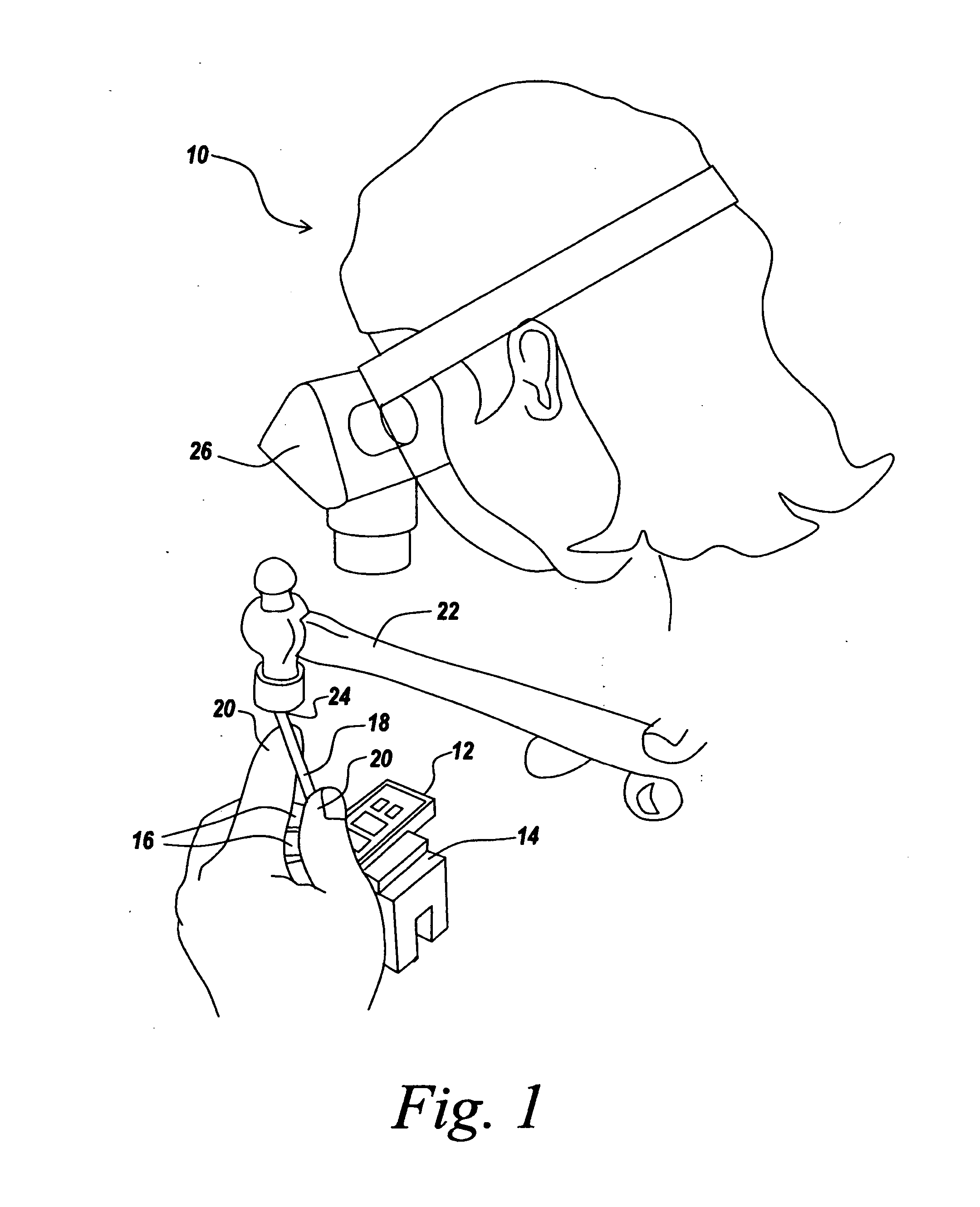
[0034] Referring now to FIG. 1, in the prior art, an operator 10 is tasked to remove a faulty component from a microwave module 12, which is held in a handheld vise 14 by the individual's fingers 16 of one hand, while a chisel 18 in the form of a miniature scalpel is held by fingers 20 of the individual's same hand. A ball peen hammer 22 strikes the top 24 of chisel 18, with the hammer being manipulated by the other hand of individual 10. All of the above operation takes place under a microscope 26.

[0035] What will be appreciated is that aside from collateral damage mentioned before, the manual operation is exceedingly difficult since the operator has to both hold the vise in one hand as well as the chisel while hammering the top of the chisel with the other hand, with all components being in the view of microscope 26.

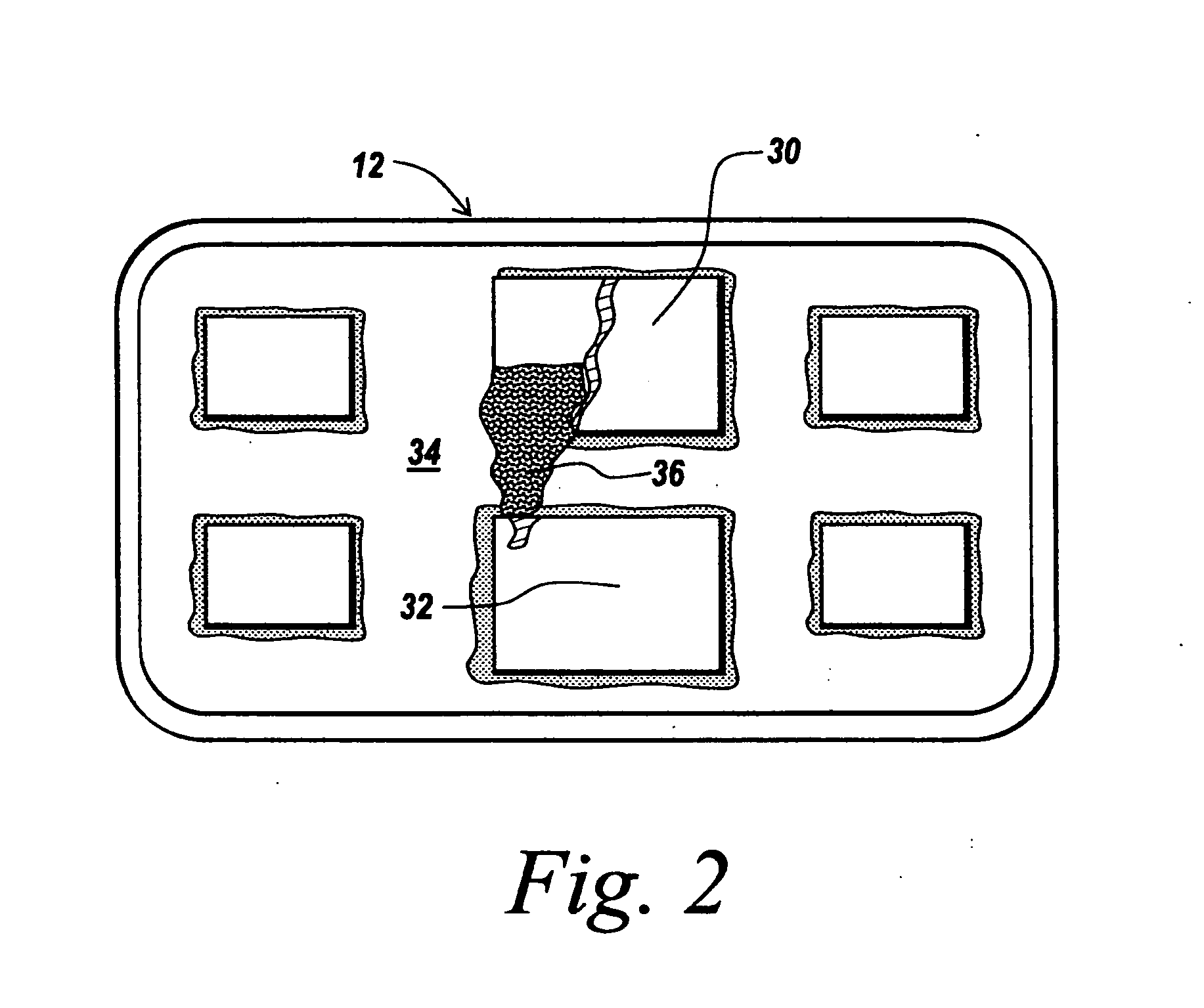
[0036] As can be seen in FIG. 2, which is a photograph of a module after an attempt to remove a damaged component by the method of FIG. 1, module 12 is left with a f...


PUM

PropertyMeasurementUnit
temperatureaaaaaaaaaa
glass transition temperaturesaaaaaaaaaa

Abstract

A specialized tool is provided for the removal of components in a microwave module in which a fixed tool having a channeled tip is positioned adjacent the component to be removed. A hot stream of gas, in one embodiment nitrogen, is then forced through the channel onto the top surface of the component to be removed, with the microwave module lying on a heated platen, such that the local increase in temperature at the component to be removed is enough hotter than the ambient temperature of the module as determined by the heated platen to soften the silver epoxy used to mount the component to the module without damaging nearby components. With the fixed tool adjacent the component to be removed and with the component provided with targeted heating, the module is moved against the tool to cause a shear force that moves the component away from its original position, thus breaking the epoxy bond, after which the component is plucked from the module. The subject tool and technique eliminates collateral damage associated with the use of a ball peen hammer and chisel, and results in a tenfold decrease in rework time.

Description

STATEMENT OF GOVERNMENT INTEREST [0001] The invention described herein was made under Contract No. F33657-00-C-0020 with the Government of the United States of America and may be manufactured and used by and for the Government of the United States of America for Governmental purposes without the payment of any royalties thereon or therefore.FIELD OF THE INVENTION [0002] This invention relates to reworking a microwave electronic part and more particularly to a method and apparatus for quickly removing the damaged component without collateral damage to the remainder of the microwave module. BACKGROUND OF THE INVENTION [0003] Microwave electronic parts come in modular form in which a number of electronic circuits and components are housed within the walls of a module, which is usually made of metal, plated typically, with gold. [0004] Inside the housing are located a number of electronic components which can be microwave integrated circuits or individual components, which are typically...

Claims


Application Information

Patent Timeline
Patent Type & Authority Applications(United States)
IPC IPC(8): H05K13/04
CPCB23K1/018B23K2201/40H05K13/0491Y10T29/49822Y10T29/53161Y10T29/53283Y10T29/49726Y10T29/49734Y10T29/4973Y10T29/53274Y10T29/49815Y10T29/49718Y10T29/4975B23K2101/40
Inventor ROCHFORD, RICHARD A.MADEJ, ROBERT F.
Owner BAE SYST INFORMATION & ELECTRONICS SYST INTERGRATION INC
Why Eureka
Try Eureka