Mass separator with controlled input

a multi-constituent material and separator technology, applied in the direction of filtration separation, separation process, centrifugal separation, etc., can solve the problems of energy adversely affecting the separation factor of systems, difficult separation of one isotope from another using chemical techniques, etc., to achieve close mass-to-charge ratio, improve separation factor, and efficient separation

Active Publication Date: 2005-08-11
GENERAL ATOMICS
View PDF13 Cites 14 Cited by
  • Summary
  • Abstract
  • Description
  • Claims
  • Application Information

AI Technical Summary

Benefits of technology

[0017] The separator is operable in either the collisional or collision-less regimes. In the collision-less regime, the relatively small radius of the plasma source, rsource, ensures that all low mass ions pass through the hollow collector. Additionally, high mass ions are not ejected from the plasma region because the mass of the high mass ions, M2, is less than the cutoff mass, MC. This is beneficial because the loss of charged, high mass particles from the plasma can upset the electrical potential which typically must be balanced for efficient separation to occur. On the other hand, when the device is used in the collisional regime, the relatively small radius of the plasma source, rsource, ensures that the ions are born cold. This results in an improved separation factor, F, allowing the separation device to be used to separate particles, such as isotopes, that have relatively close mass to charge ratios.

Problems solved by technology

As one might expect, the separation of one isotope from another using chemical techniques is somewhat difficult because different isotopes of the same chemical element typically have almost identical chemical properties.
On the other hand, techniques such as gravimetric and centrifugal separation processes that rely on a weight differential for separation are generally inefficient for isotope separation because of the relatively small weight differential that exists between isotopes of the same chemical element.
First, as indicated above, the high initial ion energy adversely affects the separation factor for systems operating above the collisional density, nc.
Another drawback associated with relatively high energy ions in a plasma is the heat that is transferred to the ion collector.
In general, collectors are only operational over a limited temperature range, and accordingly, a collector can only accommodate a limited amount of heat.
In some cases, this restriction on collector heating can limit the operational throughput of the filter (i.e. throughput is limited to levels in which collector overheating does not occur).

Method used


Image

  • Mass separator with controlled input
  • Mass separator with controlled input

Examples


Embodiment Construction

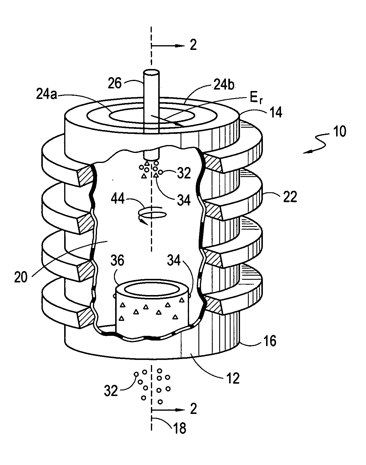
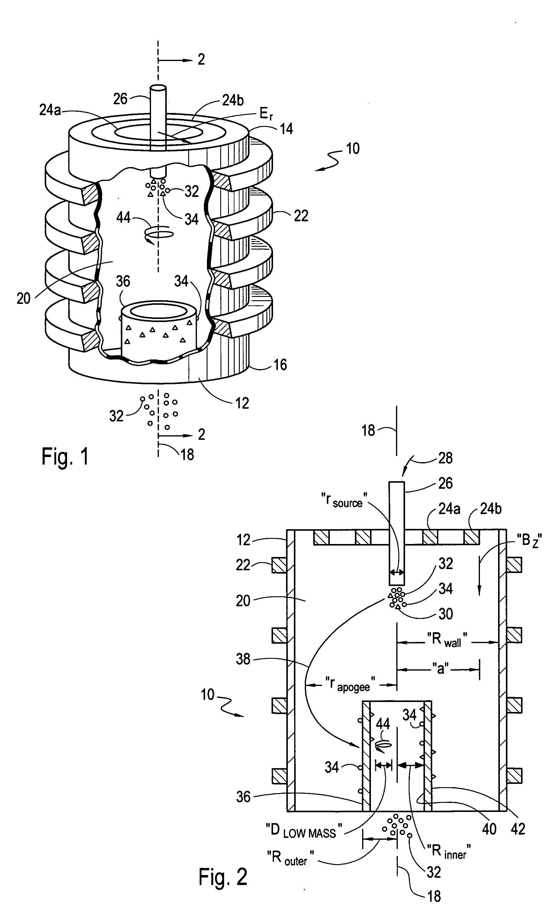
[0021] Referring initially to FIG. 1, a mass separator for separating the constituents of a multi-constituent material, such as a material that contains more than one isotope of a given chemical element is shown and generally designated 10. As shown, the separator 10 includes an enclosing wall 12 that extends from a first end 14 to a second end 16. As further shown, the wall 12 is typically formed as an elongated cylinder of inner radius, “Rwall”, that is centered on a longitudinal axis 18. It is further shown that the wall 12 surrounds a cylindrical chamber 20.

[0022] Referring still to FIG. 1, it can be seen that a plurality of coils 22, in this case four coils 22, are positioned on the outside of wall 12 to generate a uniform magnetic field, Bz, (field direction shown in FIG. 2) throughout the chamber 20. In a typical embodiment of the separator 10, the magnetic field, Bz, is substantially uniform both azimuthally and axially, and is directed substantially parallel to the longitu...


PUM

PropertyMeasurementUnit
inner radiusaaaaaaaaaa
mass to charge ratioaaaaaaaaaa
outer radiusaaaaaaaaaa

Abstract

A device for separating particles according to their respective masses includes a substantially cylindrical wall of inner radius, “Rwall”, that surrounds a chamber and defines a longitudinal axis. A multi-species plasma having relatively cold ions is initiated at a first end of the chamber within a relatively small radius, “rsource”, from the longitudinal axis. A hollow cylinder having an outer radius, “Router”, is positioned at the second end of the chamber and centered on the axis. Cross electric and magnetic fields (E×B) are established in the chamber that are configured to send ions of relatively high mass on trajectories having a radial apogee, rapogee, that is greater than the cylinder's outer radius (r>Router). After reaching apogee, these ions lose energy and strike the cylinder where they are collected. Low mass ions are placed on small radius helical trajectories and pass through the hollow cylinder.

Description

FIELD OF THE INVENTION [0001] The present invention pertains generally to devices and methods for separating the constituents of a multi-constituent material. More particularly, the present invention pertains to separation devices that convert a multi-constituent material into a plasma and thereafter separate particles in the plasma according to their respective mass to charge ratios. The present invention is particularly, but not exclusively, useful for separating particles, such as isotopes, that have relatively close mass to charge ratios. BACKGROUND OF THE INVENTION [0002] By definition, atoms of a given chemical element have the same atomic number. However, atoms of a chemical element may have different mass numbers. Specifically, different isotopes of a chemical element will have the same number of protons, but a different number of neutrons, in their respective nuclei. As one might expect, the separation of one isotope from another using chemical techniques is somewhat diffic...

Claims


Application Information

Patent Timeline
Patent Type & Authority Applications(United States)
IPC IPC(8): G21F9/00H01J49/28H01J49/32H01J49/42
CPCB01D59/48H01J49/328B03C1/288B03C1/023
Inventor OHKAWA, TIHIRO
Owner GENERAL ATOMICS
Why Eureka
Try Eureka