Pervaporation composite membrane for aqueous solution separation and methods for using the same

a technology of aqueous solution and composite membrane, which is applied in the direction of filtration separation, separation process, water/sewage treatment by ion exchange, etc., can solve the problems of high capital and energy costs, unreliable petroleum supplies from politically unstable, and the use of petroleum as a basic raw material contributes to environmental degradation, so as to improve the flux and/or separation factor, the effect of reducing the cost of biofuel separation

Inactive Publication Date: 2011-02-24
UNIV OF CONNECTICUT
View PDF28 Cites 17 Cited by
  • Summary
  • Abstract
  • Description
  • Claims
  • Application Information

AI Technical Summary

Benefits of technology

[0007]While polymers such as polyimides, polydimethylsiloxanes and the like have been used to form pervaporation membranes with some successes, to date, none have demonstrated the necessary characteristics to become a commercial success. Hence, there is a continual need for membranes with improved flux and / or separation factors and / or reduced cost in the separation of biofuel.

Problems solved by technology

However, there is increasing concern that the use of petroleum as a basic raw material contributes to environmental degradation (e.g., global warming, air and water pollution, etc.) and fosters overdependence on unreliable petroleum supplies from politically unstable parts of the world.
While it is well known to use processes such as distillation and gas stripping to effect such separation of the biofuel from the fermentation broth, these conventional processes, particularly distillation, are generally characterized by high capital and energy costs thus often making such conventional processes problematic, for example, it has been noted that in excess of 60% of the heating value of a biofuel, such as butanol, can be “wasted” if conventional separation processes are employed.
Additionally, since biobutanol has a higher normal boiling point than water, conventional distillation is not a suitable option for the recovery of the biobutanol.
While polymers such as polyimides, polydimethylsiloxanes and the like have been used to form pervaporation membranes with some successes, to date, none have demonstrated the necessary characteristics to become a commercial success.

Method used


Image

  • Pervaporation composite membrane for aqueous solution separation and methods for using the same
  • Pervaporation composite membrane for aqueous solution separation and methods for using the same
  • Pervaporation composite membrane for aqueous solution separation and methods for using the same

Examples


example 1

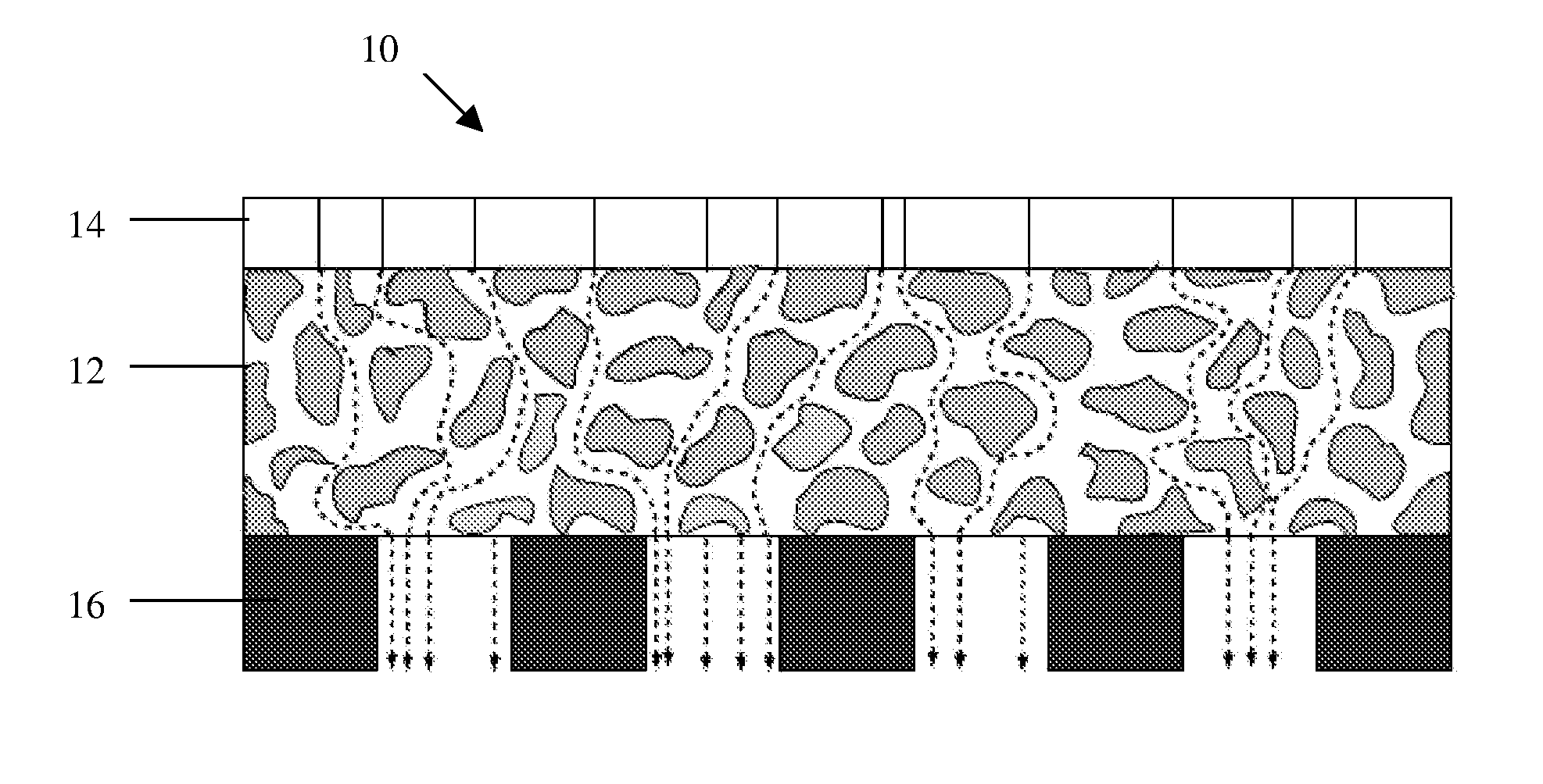
[0037]The effects of using the polyethylene layer in combination with the PDMS were determined. Several arrangements were tested. In all of the arrangements, the support layer was a brass layer having a pore size of 508 micrometers and a thickness of 406 micrometers. The PDMS layer (Sylgard® 184 commercially available from Dow Corning) had a thickness of 200 micrometers (the PDMS layer is non porous). The PE layer was either a hydrophilic polyethylene sheet with a pore size of 75 to 110 micrometers and a thickness of 610 micrometers (PE—1; hydrophilic polyethylene commercially available as POR-41210 from Porex Corporation, Fairburn, Ga.) or a hydrophobic polyethylene sheet (that is, absent fillers that render the polyethylene hydrophilic) with a pore size of 35 micrometers and a thickness of 888 micrometers (PE—2; commercially available as POR-4896 from Porex Corporation, Fairburn, Ga.). The arrangements tested, starting from the solution (e.g., feed solution) side to the permeate s...

example 2

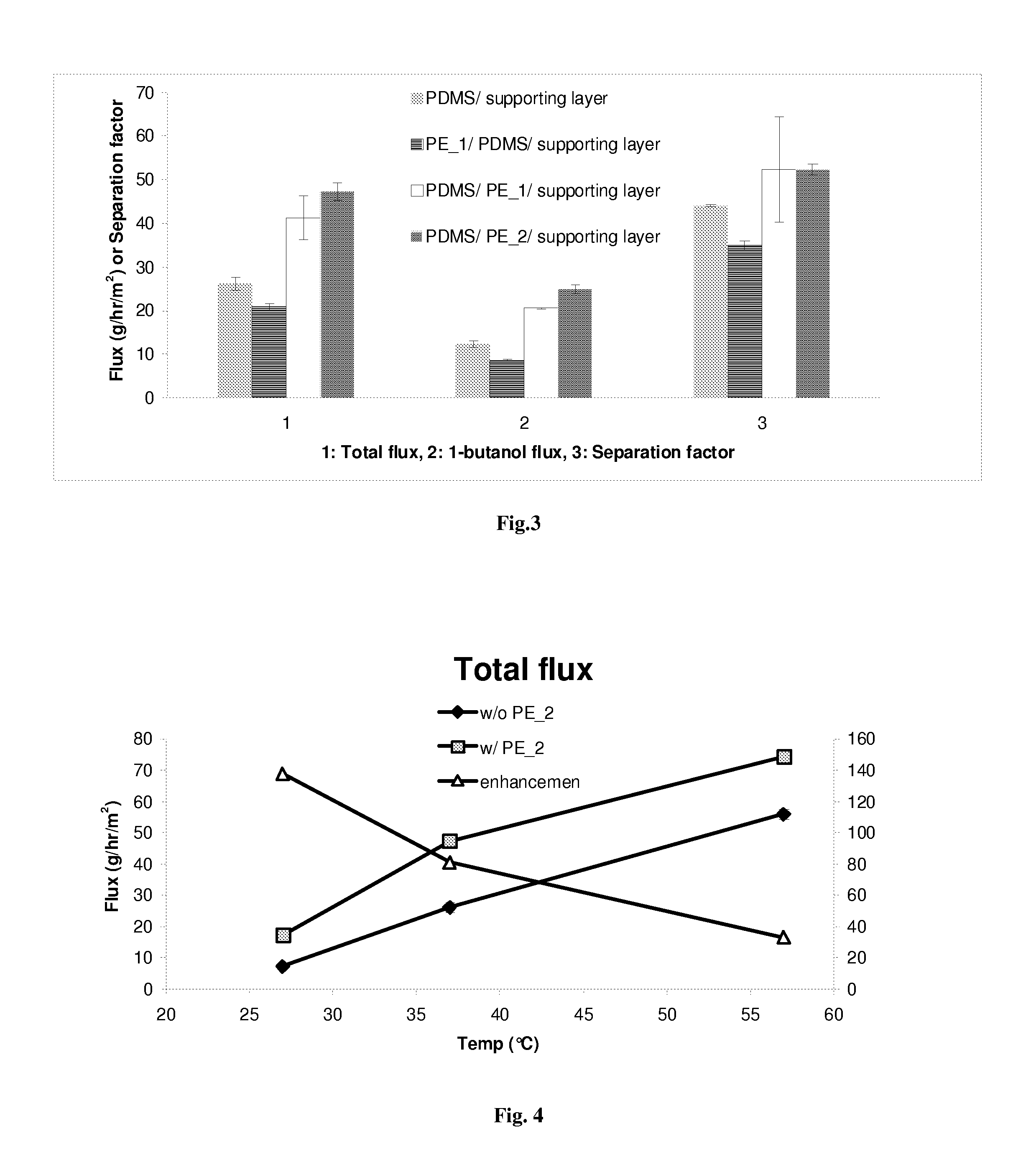
[0040]FIGS. 4-6 compare Sample 1 to Sample 4, (wherein “w / ” means with and “w / o” means without). In other words, a membrane with the PE between the PDMS and the support, versus a membrane without the PE between the PDMS and the support. These figures illustrate the unexpected, large, enhancement (e.g., in FIG. 4, enhancement is total flux w PE—2 divided by the total flux w / o PE—2) attained by using the polyethylene layer between the PDMS layer and the support.

[0041]In Table 1, the enhancement percent was determined at different temperatures. The enhancement percent was based upon the results obtained for a membrane with the PE—2 between the PDMS and the support as compared to a membrane without the PE—2 between the PDMS and the support.

TABLE 1Enhancement (%)Temperaturetotalseparation(° C.)fluxbutanol fluxfactor27137.71293.35116.003781.04102.6018.965732.9733.00−2.40

[0042]As is clear from Table 1, at about 35° C.-40° C., greater than 100% enhancement in butanol flux and nearly 19% enh...


PUM

PropertyMeasurementUnit
pore sizeaaaaaaaaaa
pore sizeaaaaaaaaaa
thicknessaaaaaaaaaa

Abstract

In one embodiment, a membrane comprises: a nonporous, hydrophobic selective layer configured to be on a feed solution side of the membrane and polyethylene layer configured to be on a permeate side of the membrane, wherein the membrane is configured to selectively separate an organic component from an aqueous solution. In some embodiments, the method for separating an organic component from an aqueous stream can comprise: contacting a nonporous, hydrophobic selective layer of a membrane with the aqueous stream comprising the organic component, creating a vacuum on the side of the membrane comprising the support layer, permeating the organic component through the membrane into an exit chamber, and removing the organic component permeate from the exit chamber.

Description

CROSS REFERERNCE TO RELATED APPLICATION[0001]This application claims the benefit of U.S. Provisional Application 61 / 235,099 filed Aug. 19, 2009, which is incorporated herein by reference in its entirety.GOVERNMENT CONTRACT[0002]This invention was made with government support pursuant to Government Contract No: 2008-34603-19452 awarded by USDA / CSREES. The Government has certain rights in this invention.BACKGROUND[0003]Conventional transportation fuels and many fine chemicals (e.g. monomers, polymers, plasticizers, adhesives, thickeners, aromatic and aliphatic solvents, etc.) are typically derived from non-renewable raw materials such as petroleum. However, there is increasing concern that the use of petroleum as a basic raw material contributes to environmental degradation (e.g., global warming, air and water pollution, etc.) and fosters overdependence on unreliable petroleum supplies from politically unstable parts of the world.[0004]Thus, biofuels and biomass-derived organic chemic...

Claims


Application Information

Patent Timeline
Patent Type & Authority Applications(United States)
IPC IPC(8): B01D61/36B01D69/12B01D71/06
CPCB01D61/362B01D69/10B01D71/70B01D69/148B01D71/26B01D69/12
Inventor PARNAS, RICHARD S.LI, SI-YU
Owner UNIV OF CONNECTICUT
Why Eureka
Try Eureka