Method and apparatus for perimeter cleaning in cold hearth refining

a technology of cold hearth and perimeter cleaning, which is applied in the field of cold hearth melting and refining apparatus and processes, can solve problems such as choking the flow of liquid stream

Inactive Publication Date: 2005-08-11
BLACKBURN ALLAN E +1
View PDF4 Cites 22 Cited by
  • Summary
  • Abstract
  • Description
  • Claims
  • Application Information

AI Technical Summary

Problems solved by technology

In time these accumulations can become large and interfere or even choke the flow of the liquid stream.

Method used


Image

  • Method and apparatus for perimeter cleaning in cold hearth refining
  • Method and apparatus for perimeter cleaning in cold hearth refining
  • Method and apparatus for perimeter cleaning in cold hearth refining

Examples


Embodiment Construction

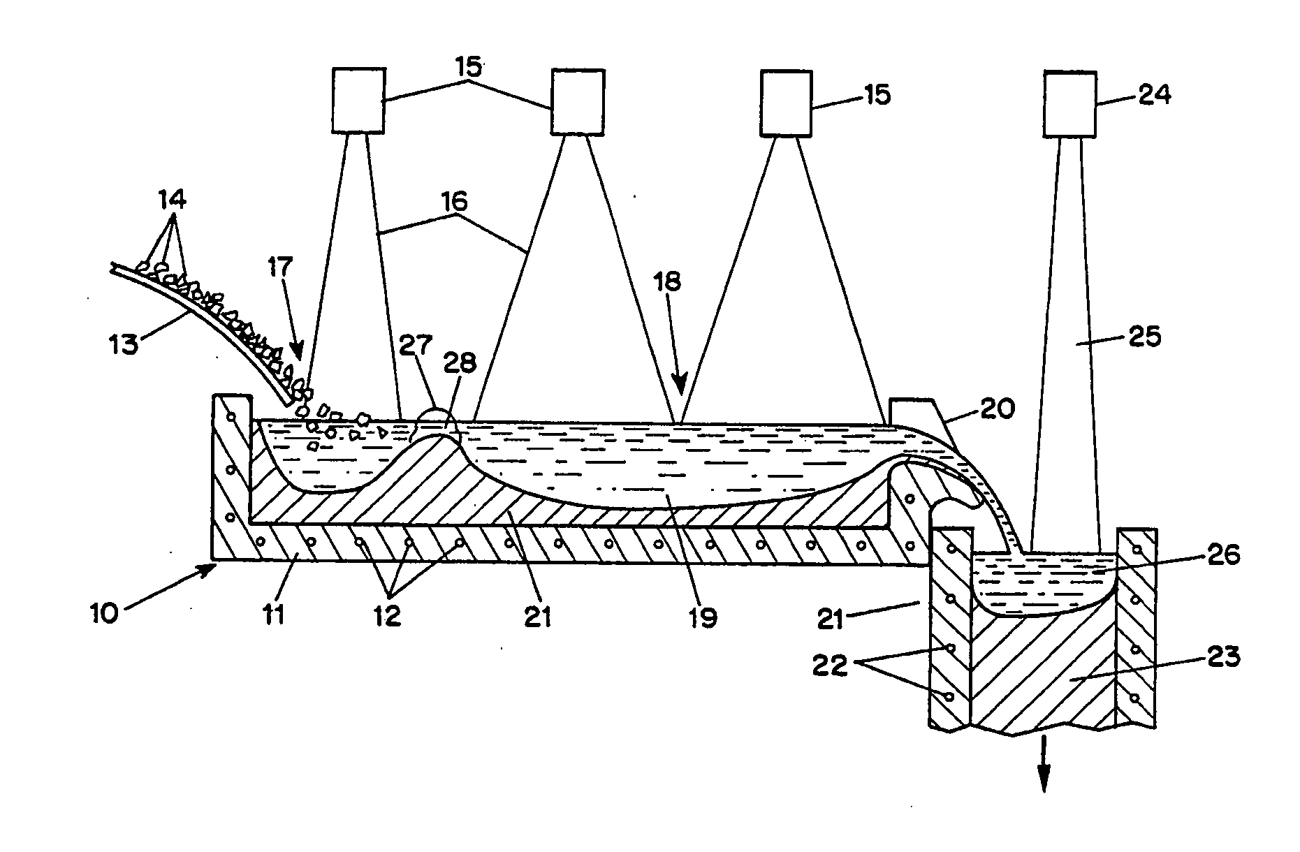
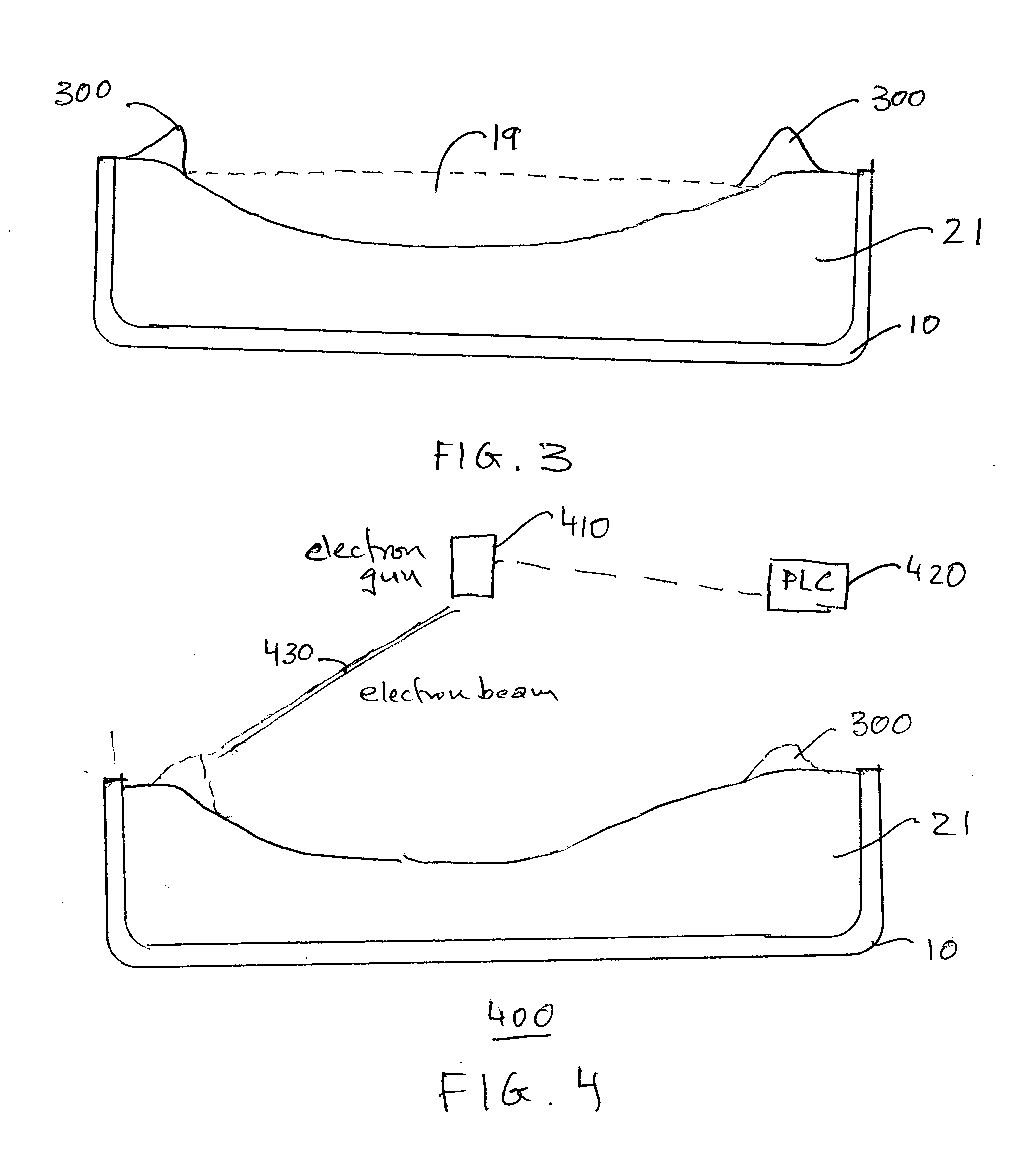
[0015] The present disclosure provides solutions for improved electron beam cold hearth melting and refining operations. A disclosed solution concerns cleaning the perimeter of the liquid stream of molten material that flows through the cold hearth.

[0016] The invention is suitable for improving the operation of EBCHR hearths, whose configurations may vary, for example, based on considerations of the type of material to the refined, throughput and other manufacturing parameters. Exemplary hearths, which can be used for refining titanium alloys, are described in Harker U.S. Pat. Nos. 4,932,635 and 4,961,776 (hereinafter “Harker”). In order that the invention herein described may be easily understood, the subsequent description is set forth with reference to the prior art cold hearths described by Harker. It will, however, be understood that the invention is equally applicable to other types or configurations of cold hearths. As an aid to the understanding of the present invention, a ...


PUM

PropertyMeasurementUnit
time periodaaaaaaaaaa
dwell timeaaaaaaaaaa
perimeteraaaaaaaaaa

Abstract

A cold hearth melting and refining arrangement for reactive or refractory metals utilizes an electron beam to automatically clean the perimeter of the pool of molten material in the hearth. A programmable logic controller is used to sweep the electron beam along at least a portion of the perimeter. The electron beam delivers energy to remelt or reevaporate volatile impurities that evaporate from the pool of molten material and redeposit on the perimeter.

Description

BACKGROUND OF THE INVENTION [0001] This invention relates to cold hearth melting and refining of reactive and refractory materials. In particular, this invention relates to improvements to electron beam cold hearth melting and refining apparatus and processes. [0002] Cold heart refining processes are now commonly employed for the production of reactive and refractory metals such as tantalum, niobium, molybdenum, tungsten, vanadium, hafnium, zirconium, titanium and their alloys. In electron beam cold hearth refining (EBCHR) processes, electron beams are used to melt target raw metals that are placed under high vacuum in water-cooled hearths. Metallic and non-metallic impurities having vapor pressures higher than those of the base constituents selectively evaporate from the molten material. Thus, the base constituent of the target material is purified. [0003] In conventional EBCHR apparatus, the hearths are usually elongated copper troughs or crucibles, which are water-cooled. The hea...

Claims


Application Information

Patent Timeline
Patent Type & Authority Applications(United States)
IPC IPC(8): C21D11/00C22B9/22C22B34/12
CPCC22B34/1295C22B9/228
Inventor BLACKBURN, ALLAN E.ODEBESI, FATAI
Owner BLACKBURN ALLAN E
Why Eureka
Try Eureka