Fractional frequency divider circuit and data transmission apparatus using the same

a technology of fractional frequency divider circuit and data transmission apparatus, which is applied in the direction of continuous circulation pulse counters, pulse techniques, and counting chain synchronous pulse counters, etc., can solve the problems of increasing consumption power and disadvantages, and achieve the effect of small size and low power consumption

Inactive Publication Date: 2005-08-11
RENESAS ELECTRONICS CORP
View PDF13 Cites 35 Cited by
  • Summary
  • Abstract
  • Description
  • Claims
  • Application Information

AI Technical Summary

Benefits of technology

[0013] Since a fractional frequency divider circuit is incorporated as a part of a usual frequency divider circuit and its output is used, the clock data reco

Problems solved by technology

Also, a conventional data transmission apparatus that has multiple channels and is able to change data speed for each channel is constituted su

Method used


Image

  • Fractional frequency divider circuit and data transmission apparatus using the same
  • Fractional frequency divider circuit and data transmission apparatus using the same
  • Fractional frequency divider circuit and data transmission apparatus using the same

Examples


embodiment 1

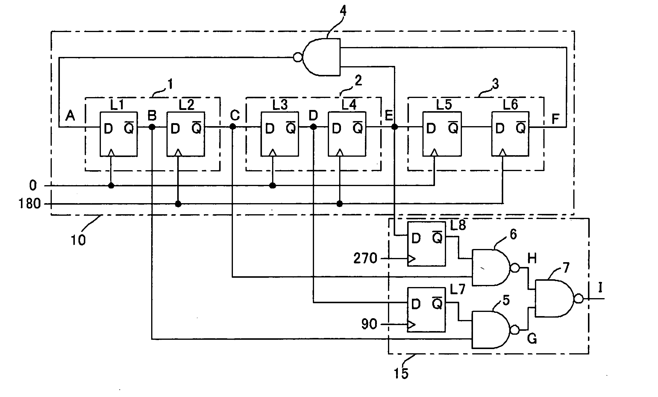
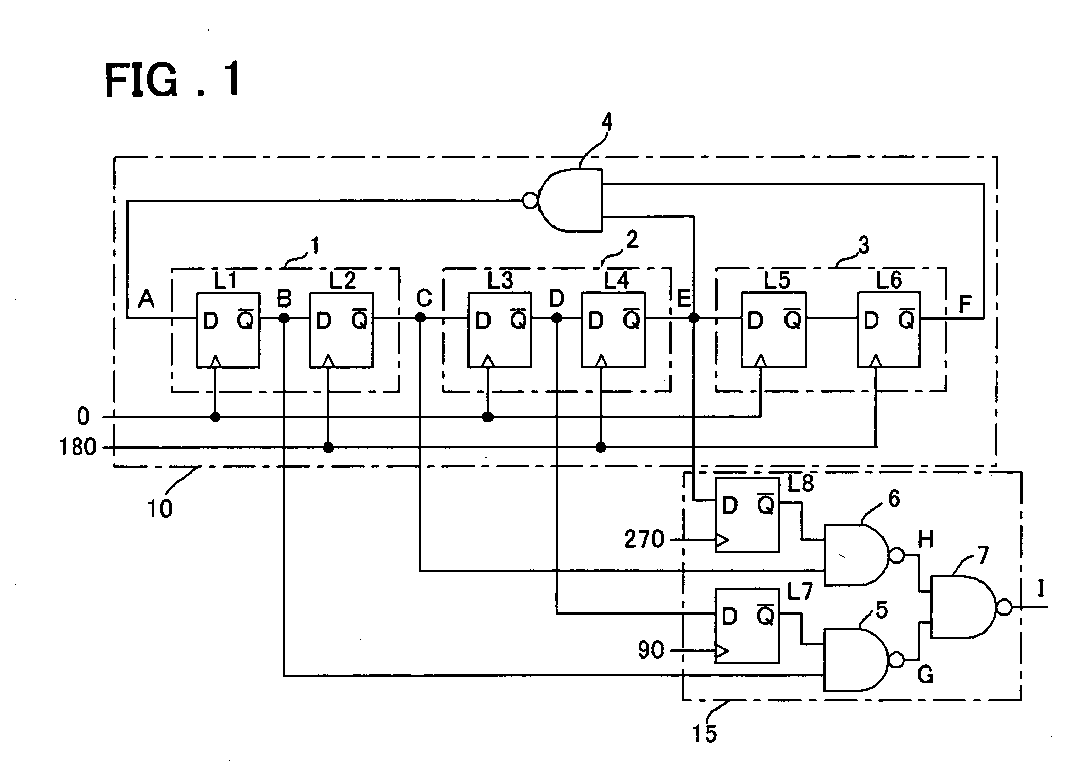
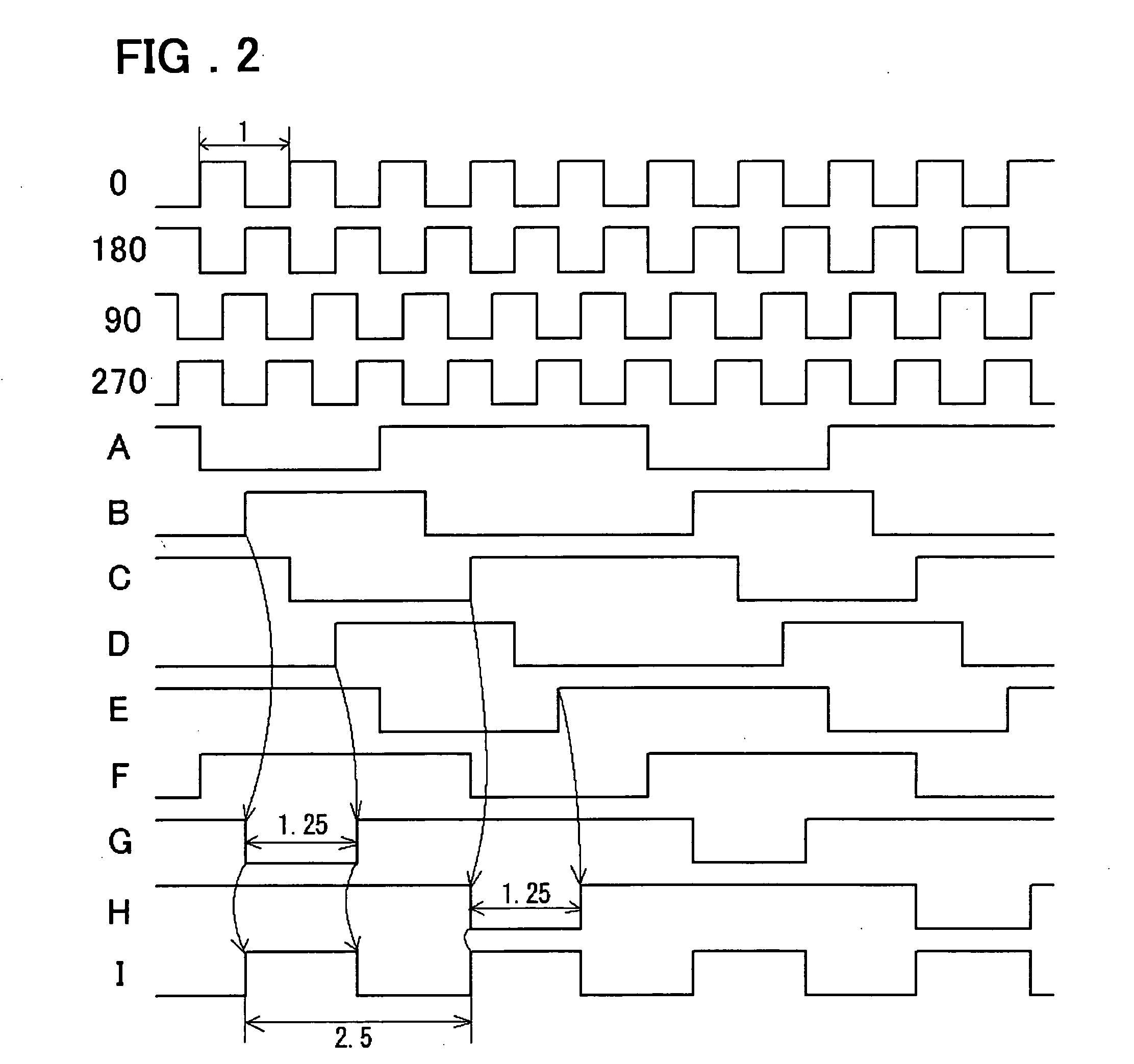
[0020] Hereinafter, embodiments of the present invention will be described with reference to drawings. FIG. 1 is a drawing showing a constitution of Embodiment 1 and FIG. 2 is a timing chart for explaining its operation. A fractional frequency divider circuit shown in FIG. 1 is able to output a 1 / 2.5 frequency-divided clock signal by taking out signals from an internal node B, internal node C, internal node D, and internal node E of a ⅕ frequency divider circuit 10, and processing them at a logic circuit 15.

[0021] The ⅕ frequency divider circuit 10 comprises master-slave flip-flops 1, 2, 3 and a NAND gate 4. L1 and L2, L3 and L4, and L5 and L6 are data latches that constitute master stages and slave stages respectively. The logic circuit 15 comprises data latches L7 and L8, and NAND gates 5, 6, and 7. At the data latches L1 through L7, D is a data input terminal and / Q is an inverted signal output terminal.

[0022] The 1 / 2.5 frequency divider circuit shown in FIG. 1 operates as a 4-p...

embodiment 2

[0025] In Embodiment 2, the present invention is applied to a data transmission apparatus with multiple channels wherein it is possible to set data speed for each channel separately. FIG. 3 is a block diagram of the present embodiment. A transmitter circuit (TX) and receiver circuit (RX) for one channel are shown in FIG. 3. In the present embodiment, two data speeds can be supported by providing a 1 / 2.5 frequency divider circuit at a PLL part and arranging two kinds of clock, and by providing a selection circuit for each of the TX and RX, and switching over between frequency-multiplied clocks (3.125 GHz and 1.25 GHz in FIG. 3).

[0026] The receiver circuit (RX) is comprised of a clock data recovery circuit (CDR) and a serial-parallel conversion circuit (DEMUX). The clock data recovery circuit (CDR) comprises a phase interpolator part (PI), a receiver flip-flop (FF), and a control circuit (CNT). At the phase interpolator part (PI), an inputted differential clock signal is frequency-div...


PUM


Abstract

A fractional frequency divider circuit with a small circuit scale that outputs a clock with a duty ratio of 50%, and a data transmission apparatus comprising same. The fractional frequency divider circuit is constituted by multiple master-slave flip-flops, and comprises an integer frequency divider circuit that frequency-divides a clock signal with a frequency-division ratio of 1/N(N is an integer), and a logic circuit into which multiple signals outputted from master stages and slave stages of the master-slave flip-flops are inputted and that outputs a signal with a duty ratio of 50% obtained by frequency-dividing the clock signal with a frequency-division ratio of 2/N. The data transmission apparatus is constituted such that it is possible to switch over between a frequency-multiplied clock outputted by a PLL and a clock obtained by frequency-dividing the frequency-multiplied clock with the fractional frequency divider circuit for each channel.

Description

FIELD OF THE INVENTION [0001] The present invention relates to a fractional frequency divider circuit and a data transmission apparatus using the same, and especially to a fractional frequency divider circuit suitable for supplying multiple kinds of clock to a data transmission apparatus used for high-speed communication, and a data transmission apparatus using the same. BACKGROUND OF THE INVENTION [0002] A conventional high-speed interface circuit is formed of a receiver circuit (RX) that receives external data and performs serial-parallel conversion thereof, a transmitter circuit (TX) that performs parallel-serial conversion of internal data, and a PLL that multiplies an external reference clock and supplies it to the RX and TX. In an apparatus comprising multiple channels constituted such that an RX is coupled with a TX, one PLL generally supplies a clock commonly to the multiple channels. However, in this case, the data speed cannot be changed for each channel. It is thought to ...

Claims


Application Information

Patent Timeline
IPC IPC(8): H03K21/02H03K21/00H03K23/54H03L7/08H03L7/197
CPCH03L7/1974H03K23/546H03K23/64H03L7/183H03L7/197
Inventor SAEKI, TAKANORI
Owner RENESAS ELECTRONICS CORP
Why Eureka
Try Eureka