Radio-controlled clock and method for determining the signal quality of a transmitted time signal

a radio-controlled clock and signal quality technology, applied in the field of radio-controlled clocks and methods for determining the signal quality of transmitted time signals, can solve the problems of interference signals, inability to correctly recognize and evaluate the second marker of signals, and inability to receive time signals. to achieve the effect of simple method of determining signal quality

Inactive Publication Date: 2005-08-11
ATMEL GERMANY +1
View PDF38 Cites 33 Cited by
  • Summary
  • Abstract
  • Description
  • Claims
  • Application Information

AI Technical Summary

Benefits of technology

[0057] The functions of the inventive signal quality evaluating arrangement can be advantageously realized or embodied in a hard-wired logic circuit. For example, such a logic circuit can be incorporated in a Field Programmable Gate Array (FPGA) circuit or a Programmable Logic Device (PLD) circuit. Furthermore, alternatively, the functions of the signal quality evaluating arrangement can be carried out or incorporated in the microcontroller that is typically already included in a radio-controlled clock. The special advantage of the inventive preferred solution using a separate hard-wired logic circuit, is that thereby the signal quality can be determined in a very simple manner, without burdening the microcontroller for this task. Thus, the microcontroller remains fully available for carrying out other tasks, for example for the decoding and evaluation of the time signal, as well as other user-specific tasks.

Problems solved by technology

In this regard it is problematic that the received time signals can be obscured or falsified by interference signals superimposed thereon.
Such interference signals arise from the interference fields emitted by electrical or electronic devices, for example in the direct surrounding vicinity of the time signal receiver.
Depending on the type, scope and strength of these interference signals, the reception of the time signal will be more or less interfered with, and it may become impossible to correctly recognize and evaluate the second markers of the signal.
Through such erroneous evaluation decisions, due to the interference, at least one of the data bits of the minute protocol is erroneously decoded or not decoded at all.
A problem or shortcoming of the above conventional system and method is that the field strength indication does not provide any direct information about interference to the user, i.e. whether the time signal telegram of the time signal itself has been received without interference.
However, that received field strength could actually also include interference in the received signal.
Thus, the above mentioned conventional method and system are not suitable for evaluating the actual signal quality of the received time signal, especially in situations in which the field strength of an interference signal quantitatively lies within the range of the field strength of the useful time signal.
Thus, the provided field strength information does not give an accurate or valid indication of the true time signal quality in a consistent and reliable manner.
Such an evaluation would give a true indication of the signal quality of the received useful signal, but the prior art has not developed any solutions in this direction.

Method used


Image

  • Radio-controlled clock and method for determining the signal quality of a transmitted time signal
  • Radio-controlled clock and method for determining the signal quality of a transmitted time signal
  • Radio-controlled clock and method for determining the signal quality of a transmitted time signal

Examples


Embodiment Construction

[0068] In all of the drawing figures, the same elements and signals, as well as the elements and signals respectively having the same functions, are identified by the same reference numbers, unless the contrary is indicated.

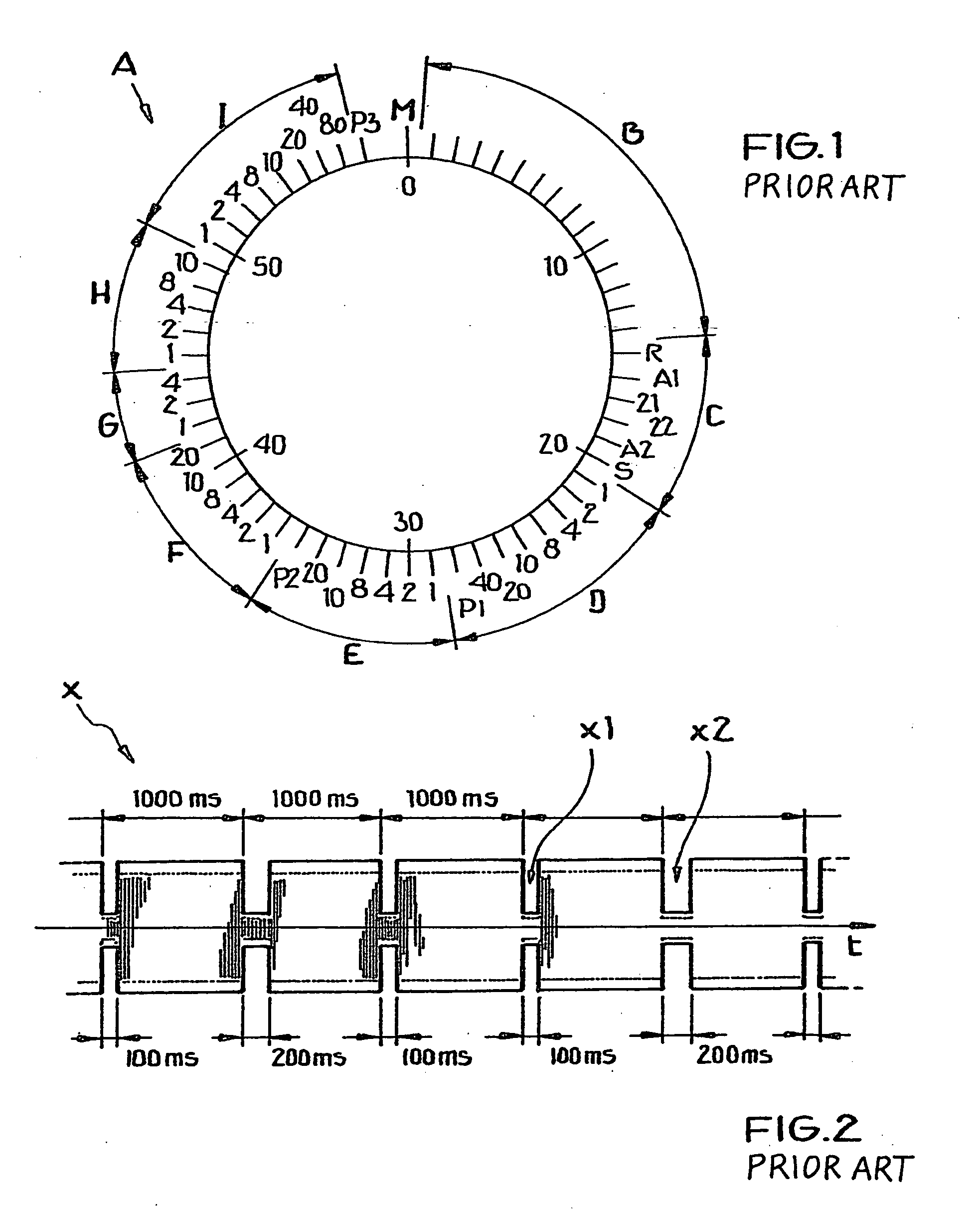
[0069] The general format of an encoding scheme or time code telegram A as conventionally known in the time signal transmitted by the German time signal transmitter DCF-77 has been explained above in connection with FIG. 1 in the Background Information section of this specification. Also, the time-variation of the amplitude-modulated time signal is schematically shown in the time diagram of FIG. 2 as discussed above.

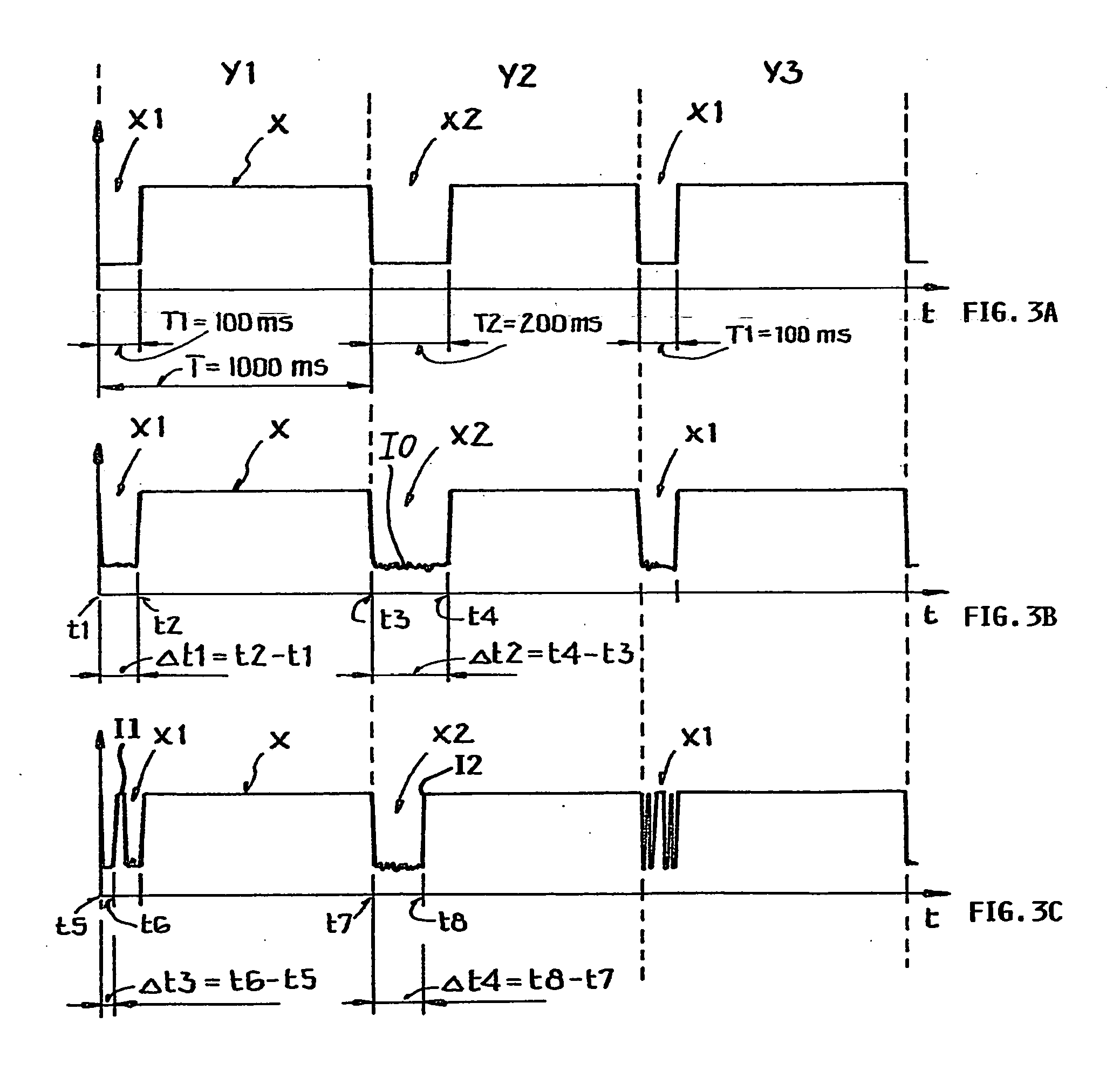
[0070]FIG. 3 includes three sub-figures, namely FIGS. 3A, 3B and 3C respectively showing variants of a time signal. FIG. 3A shows a portion of an idealized time signal as transmitted by the German time signal transmitter DCF-77, for example in accordance with the time signal telegram discussed above in connection with FIGS. 1 and 2. FIGS. 3B and 3C ...


PUM


Abstract

A transmitted time signal carries time information encoded bit-wise by signal variations in a succession of constant duration time frames, with at least one bit in each time frame. A signal quality is determined and allocated to a respective bit, e.g. depending on the extent of deviation of an actual duration from prescribed durations of a signal variation representing the bit. Thus, a respective signal quality may be allocated to a respective decoded data bit per time frame. Successive data bits can be categorized as interference-free or interference-burdened, and a signal quality of the received time signal can alternatively be determined from the number or ratio of the interference-free bits and the interference-burdened bits. A radio-controlled clock circuit includes a receiving circuit, a bit value decoding arrangement and a signal quality evaluating arrangement.

Description

PRIORITY CLAIM [0001] This application is based on and claims the priority under 35 U.S.C. §119 of German Patent Application 10 2004 004 416.3, filed on Jan. 29, 2004, the entire disclosure of which is incorporated herein by reference. FIELD OF THE INVENTION [0002] The invention relates to methods for determining the signal quality of a time signal transmitted by a time signal transmitter. The invention further relates to a receiver circuit and / or a radio-controlled clock for carrying out such a method. BACKGROUND INFORMATION [0003] It is conventionally known to provide time reference information in time signals that are transmitted by radio transmission from a time signal transmitter. Such a signal may also be called a time marker signal, a time data signal, a time code signal, or a time reference signal, for example, but will simply be called a time signal herein for simplicity. The time signal transmitter obtains the time reference information, for example, from a high precision ...

Claims


Application Information

Patent Timeline
Patent Type & Authority Applications(United States)
IPC IPC(8): G04G3/02G04G5/00G04R20/12H04Q11/00
CPCG04G5/002G04R20/12G04G7/023
Inventor HAEFNER, HORSTPOLONIO, ROLANDSAILER, HANS-JOACHIM
Owner ATMEL GERMANY
Why Eureka
Try Eureka