Temperature control method and apparatus and exposure method and apparatus

Inactive Publication Date: 2005-08-11
NIKON CORP
View PDF2 Cites 16 Cited by
  • Summary
  • Abstract
  • Description
  • Claims
  • Application Information

AI Technical Summary

Benefits of technology

[0026] According to the exposure apparatus of the present invention, it is possible to improve the temperature control accuracy for the first object, the second object, or the driving mechanism therefor. Therefore, it is possible to improve the overlay accuracy and the positioning accuracy of the first object or the second object.
[0027] According to still another aspect of the present invention, there is prov

Problems solved by technology

However, if the chemical filter is installed in the flow passage for the gas in a system in which only the measured value of the temperature in the environmental chamber is merely subjected to the feedback to the temperature control unit as in the conventional technique, an inconvenience has arisen such that the temperature of the gas in the environmental chamber tends to be varied, and the temperature control accuracy is lowered.
However, if the chemical filter is used in accordanc

Method used


Image

  • Temperature control method and apparatus and exposure method and apparatus
  • Temperature control method and apparatus and exposure method and apparatus
  • Temperature control method and apparatus and exposure method and apparatus

Examples


Embodiment Construction

[0032] An explanation will be made below with reference to the drawings about an exemplary preferred embodiment of the present invention.

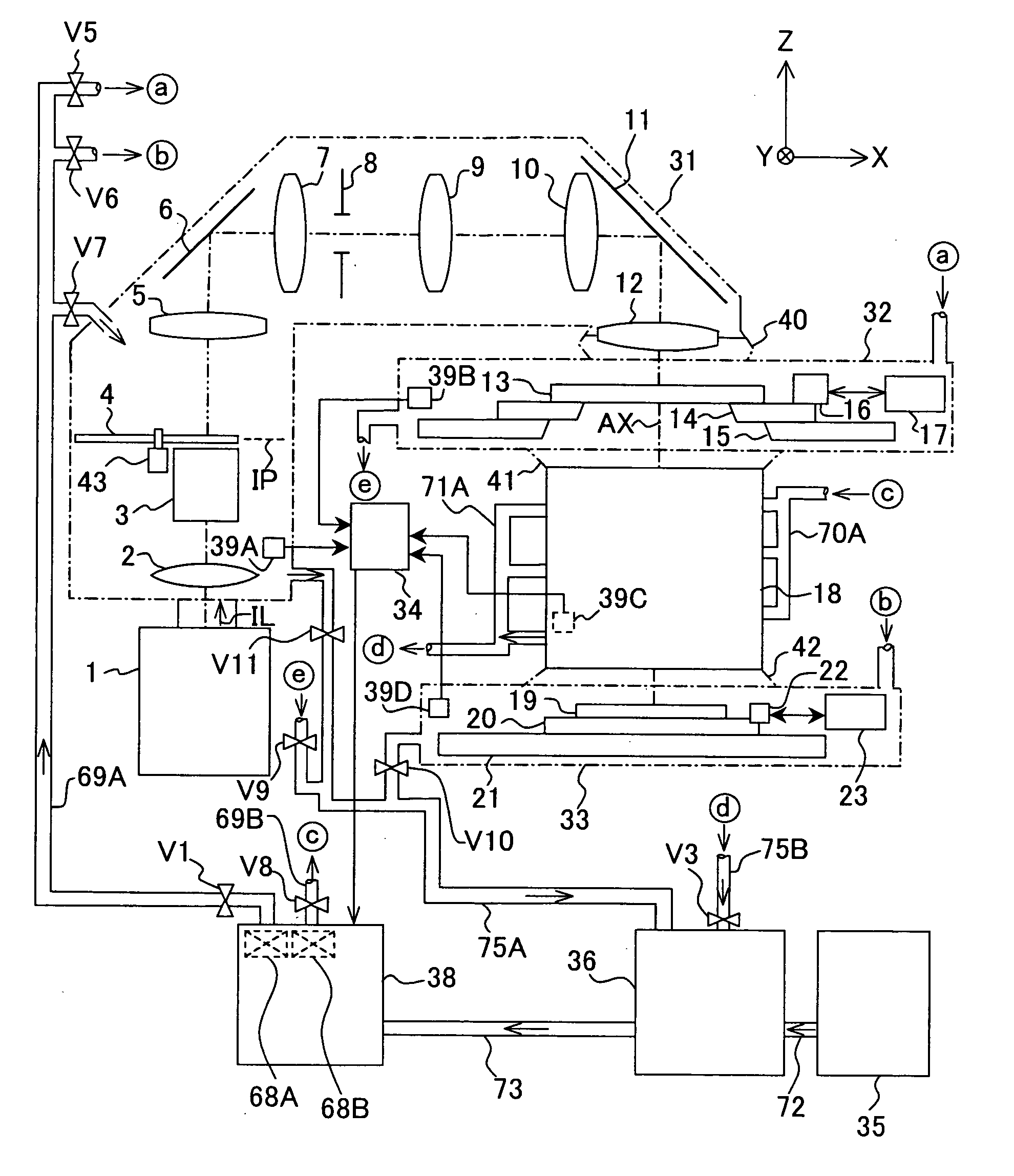
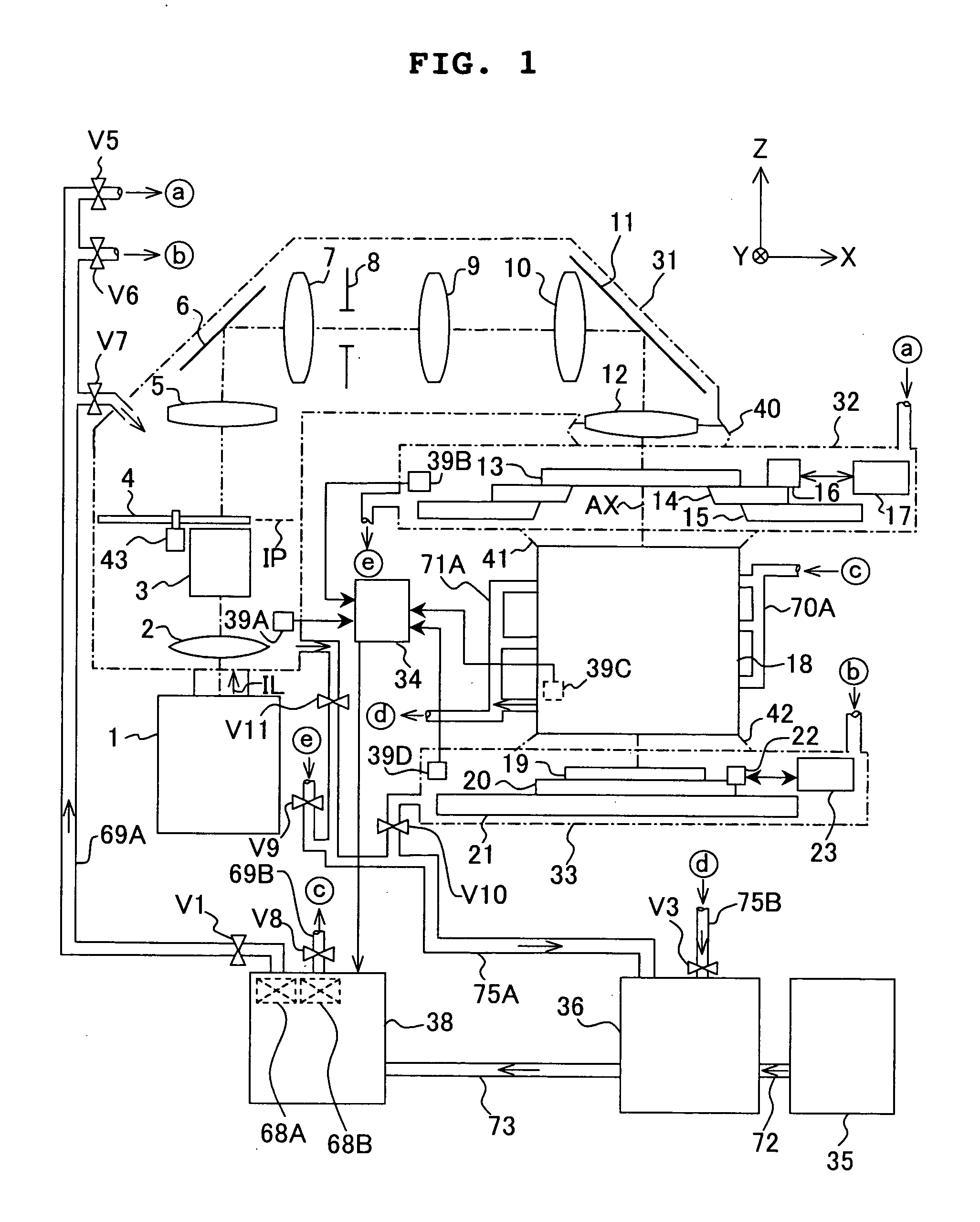
[0033] The present invention is widely applicable, for example, when the temperature is controlled in a clean room in which the lithography system is accommodated, when the temperature is controlled in an environmental chamber in which the entire exposure apparatus is accommodated, and when the optical path of the exposure light beam of the exposure apparatus is divided into a plurality of gas-tight chambers, and the temperature-controlled gas with high transmittance is supplied to the respective gas-tight chambers. In the following embodiment, the explanation will be mage about a case in which the present invention is applied to a projection exposure apparatus based on the step-and-scan system provided with gas-tight chambers to which the temperature-controlled gas is supplied.

[0034]FIG. 1 schematically shows a structure illustrating the project...


PUM


Abstract

A temperature control technique and an exposure technique are provided with which high temperature control accuracy can be realized even when a device, which causes thermal fluctuation depending on a temperature-controlled fluid, is used. A gas recovered from a reticle chamber as the temperature control objective, and a high purity purge gas supplied from a gas supply source are mixed in a mixing section. The temperature of the mixed gas is lowered by a refrigerator. Subsequently, the humidity of the gas is measured by a temperature sensor. The gas is then supplied to the reticle chamber via a heating mechanism, a chemical filter which absorbs or generates heat depending on the humidity and a dust protective filter. The heating amount to the gas by the heating mechanism is controlled based on temperature information by a temperature sensor in the reticle chamber and humidity information by the humidity sensor.

Description

CROSS-REFERENCE [0001] This application is a Continuation Application of International Application No. PCT / JP2003 / 010757 which was filed on Aug. 26, 2003 claiming the conventional priority of Japanese patent Application No. 2002-250179 filed on Aug. 29, 2002.BACKGROUND OF THE INVENTION [0002] 1. Field of the Invention [0003] The present invention relates to a temperature control technique for controlling the temperature in a predetermined space. The present invention is preferably usable, for example, when the temperature is controlled in an air-tight or gas-tight room (chamber or the like) in which an exposure apparatus or a part of the mechanism thereof is accommodated, the exposure apparatus or the part of the mechanism thereof being used for the lithography step to produce various devices including, for example, semiconductor elements, image pickup elements (CCD or the like), liquid crystal elements, plasma display elements, and thin film magnetic heads. Further, the present inv...

Claims


Application Information

Patent Timeline
IPC IPC(8): G03F7/20
CPCG03F7/70933G03F7/70858
Inventor ARAI, DAIYOSHIDA, TOMOYUKI
Owner NIKON CORP
Why Eureka
Try Eureka