Ultrasound gating of cardiac CT scans

a technology of ultrasonic gating and cardiac ct scan, which is applied in the field of ultrasonic gating of cardiac ct scan and ultrasonic gating of ct system, can solve the problems of insufficient resolution, insufficient reproducibility, and limited ct technique, so as to optimize the visualization of one part of the heart, and improve the effect of resolution

Inactive Publication Date: 2005-08-11
RGT UNIV OF MICHIGAN
View PDF4 Cites 27 Cited by
  • Summary
  • Abstract
  • Description
  • Claims
  • Application Information

AI Technical Summary

Benefits of technology

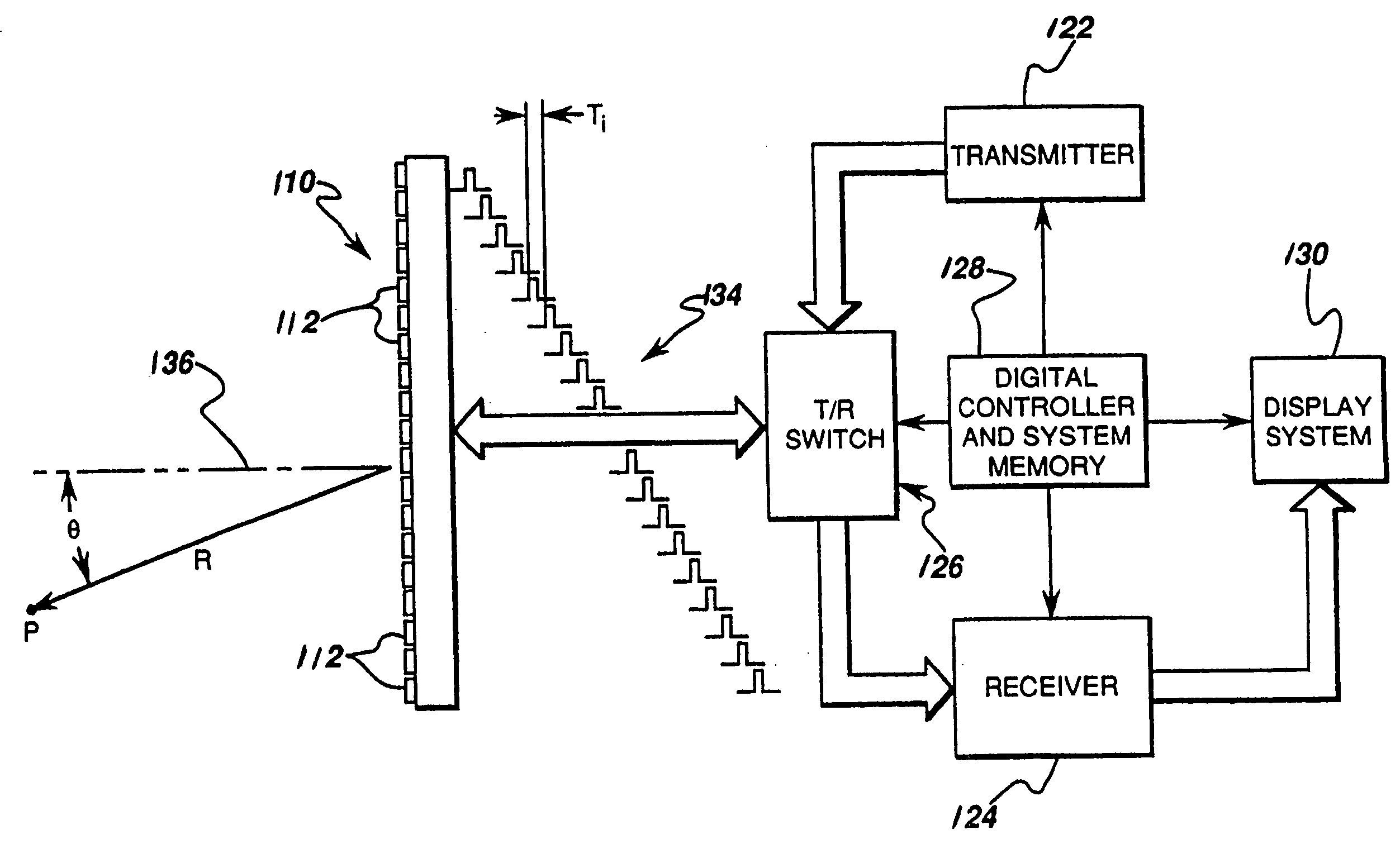
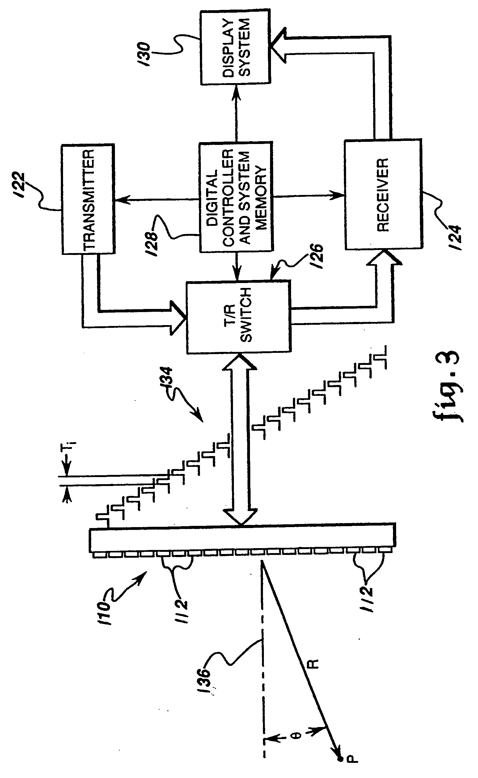
[0014] A general object of the invention is to provide a more accurate and objective gating signal. The advantages of the method are that the gating signal is generated from object motion itself with very little processing of the echo signals. Thus, there is no issue about time delays and variations between an electric signal and the wall motion. One can gate from specific structures in or portions of the heart so the timing can be designed to optimize the visualization of one part of the heart. Also clever strategies can be employed that permit gating during different parts of the acquisition cycle for different parts of the heart. These enable one to obtain an optimized heart image or a very high resolution image of one part of the heart.

Problems solved by technology

However, the CT technique is presently limited.
The main problem is that reconstruction of 3D CT coronary angiograms are not good enough or reproducible enough to meet the imaging standards necessary to replace standard coronary angiography.
However, using standard ECG gating in the beating heart, even with intravenous contrast injections, such resolutions cannot be approached.
Multiple studies have documented the difficulties inherent in standard ECG gating.
Higher, more typical heart rates, are more problematic with scans produced from hearts beating at such standard rates of 71-80 beats / min have about 35% of images on average degraded by artifacts.
Although the fastest present acquisition rates by electron beam CT scanners can approach this limit, 100 msec per slice, the image quality of electron beam scanners does not match that of the standard mechanical scanners, making their faster speeds of limited advantage.
Unfortunately, ECG gating has an inherent, intrinsic problem, which is that ECG gating is based on the heart's changing electrical potential, whereas the activity being gated is the heart's physical motion.
However, when near perfect precision is required in the reconstruction, even minor fluctuations will cause unacceptable degradations.

Method used


Image

  • Ultrasound gating of cardiac CT scans
  • Ultrasound gating of cardiac CT scans
  • Ultrasound gating of cardiac CT scans

Examples


Embodiment Construction

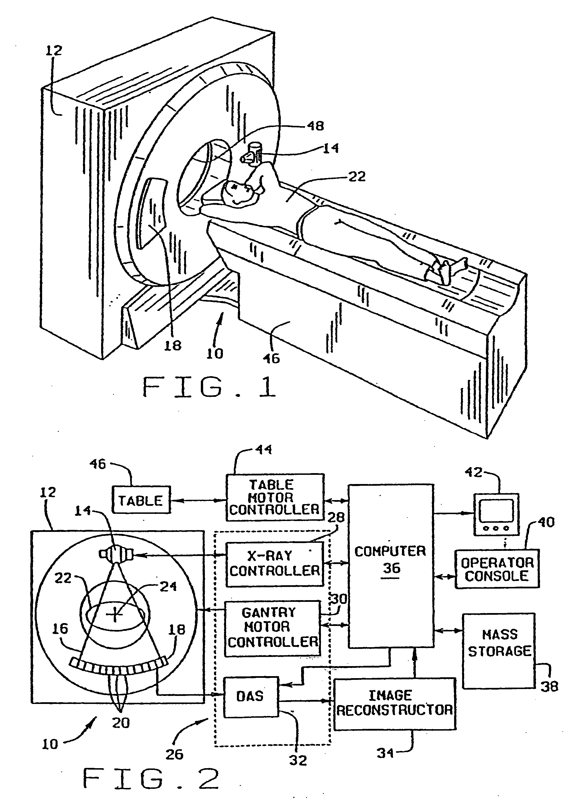
[0023] With initial reference to FIGS. 1 and 2, a computed tomography (CT) imaging system 10 includes a gantry 12 representative of a “third generation” CT scanner. Gantry 12 has an x-ray source 13 that projects a cone beam of x-rays 14 toward a detector array 16 on the opposite side of the gantry. The detector array 16 is formed by a number of detector elements 18 which together sense the projected x-rays that pass through a medical patient 15. Each detector element 18 produces an electrical signal that represents the intensity of an impinging x-ray beam and hence the attenuation of the beam as it passes through the patient. During a scan to acquire x-ray projection data, the gantry 12 and the components mounted thereon rotate about a center of rotation 19 located within the patient 15.

[0024] The rotation of the gantry and the operation of the x-ray source 13 are governed by a control mechanism 20 of the CT system. The control mechanism 20 includes an x-ray controller 22 that prov...


PUM

PropertyMeasurementUnit
timeaaaaaaaaaa
timeaaaaaaaaaa
ultrasonic echoaaaaaaaaaa

Abstract

An ultrasonic imaging system acquires echo signals from an object being imaged such as a moving coronary artery and the cross-correlation between echo signals is employed as an objective measure of relative object location. The method is used in a prescan procedure to determine an optimal gating window to acquire image data during a cardiac gated scan, and it is used during the scan as a real time gating signal.

Description

CROSS-REFERENCE TO RELATED APPLICATIONS [0001] This application is based on U.S. Provisional Patent Application Ser. No. 60 / 534,583 filed on Jan. 6, 2004 and entitled “Ultrasound Gating Of Cardiac CT Scans”.BACKGROUND OF THE INVENTION [0002] The present invention relates to computed tomography (CT) imaging apparatus; and more particularly, to the gating of CT systems during cardiac scans. [0003] In a current computed tomography system, an x-ray source projects a fan-shaped beam which is collimated to lie within an X-Y plane of a Cartesian coordinate system, termed the “imaging plane.” The x-ray beam passes through the object being imaged, such as a medical patient, and impinges upon an array of radiation detectors. The intensity of the transmitted radiation is dependent upon the attenuation of the x-ray beam by the object and each detector produces a separate electrical signal that is a measurement of the beam attenuation. The attenuation measurements from all the detectors are acqu...

Claims


Application Information

Patent Timeline
Patent Type & Authority Applications(United States)
IPC IPC(8): A61B6/00A61B8/00A61B8/02A61B8/12A61B8/14G01N23/00G21K1/12H05G1/60
CPCA61B6/488A61B6/503A61B8/02A61B6/541A61B6/504
Inventor RUBIN, JONATHAN M.FOWLKES, JEFFREY BRIANMEYER, CHARLES R.TRIDANDAPANI, SRINI
Owner RGT UNIV OF MICHIGAN
Why Eureka
Try Eureka