Cryosurgical devices and methods for endometrial ablation

a technology of endometrium and surgical equipment, which is applied in the field of cryosurgical equipment and methods for endometrial ablation, can solve the problems of difficult coverage, discomfort or possible tissue damage to the vagina, and a significant amount of time and skill in manipulating the rolling device to ensure the destruction of the entire endometrium

Inactive Publication Date: 2005-08-11
COOPERSURGICAL INC
View PDF13 Cites 150 Cited by
  • Summary
  • Abstract
  • Description
  • Claims
  • Application Information

AI Technical Summary

Benefits of technology

[0015] The probe tip of the system may be coupled to the cannula by a coupling mechanism that fluidly isolates the fluid paths of the extensions from the probe handle and refrigerant source to create a closed first fluid syste

Problems solved by technology

While this type of procedure can be effective, it requires a significant amount of time and skill in manipulating the rolling device to ensure that the entire endometrium is destroyed.
However, such coverage can be difficult due to temperature fluctuations and gradients along the surface of the balloon that can be caused by many factors, such as convective currents of the fluid within the balloon, and maintaining adequate thermal contact between the outer surface of the balloon and the uterine tissue.
In addition, the movement of hot fluid into the balloon can sometimes cause discomfort or possible tissue damage to the vagina and opening of the cervix as heat is conducted through the walls of the catheter to which the balloon is attached.
Thus, if system joints are broken or separated for any reason, such as during the replacement or repair of parts, contaminants will often be flushed from the system along with the exhaust of gas.
Therefore, any contaminants that are unintentionally introduced into the system can collect within the system over a period of time and may undesirably be deposited within the system in such a place that eventually blocks or partially blocks the unrestricted flow of gas through the system.
Thus, these closed loop systems may be provided as permanently sealed systems that are designed to prevent the introduction of contaminants, which

Method used


Image

  • Cryosurgical devices and methods for endometrial ablation
  • Cryosurgical devices and methods for endometrial ablation
  • Cryosurgical devices and methods for endometrial ablation

Examples


Embodiment Construction

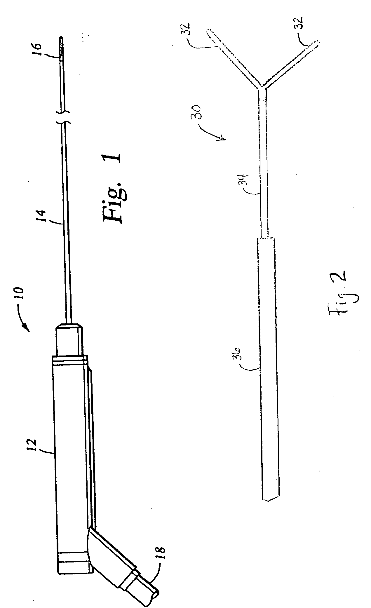
[0028] Referring now to the Figures, wherein the components are labeled with like numerals throughout the several Figures, and initially to FIG. 1, one configuration of a cryosurgical probe 10 that can be used for cryoablation of endometrial tissue in the uterus of a female patient is shown. The probe 10 generally includes a handle 12, a hollow tubular cannula 14, and a cold tip 16. The handle 12 can be metallic to facilitate effective sealing of the components to minimize any gas or fluid leakage that might otherwise occur. The handle 12 can also be provided with insulating properties so that it is comfortable for the user to manipulate, such as may be provided by the inclusion of insulation (e.g., aerogel) in the handle or in the form of a vacuum space within the handle. Several components of the refrigeration system, such as heat exchangers, can optionally be housed within the handle 12, as will be discussed in further detail below. Other components may also be housed within the ...


PUM


Abstract

A cryoablation system including a cannula having a proximal end, a distal end, and a longitudinal axis, an expandable balloon extending from the distal end of the cannula and fluidly connected to a source of heat transfer fluid by at least one fluid path, a pump for circulating the heat transfer fluid into and out of the balloon, a probe handle coupled to the proximal end of the cannula and in fluidic communication with the balloon through the cannula, and a heat exchanger for varying the temperature of the heat transfer fluid, wherein the heat exchanger is fluidly connected to a secondary refrigerant source. The heat exchanger may be positioned within the probe handle, within the cannula, or at least partially within the balloon. The heat transfer fluid of this cryoablation system preferably has a freezing point lower than about −110° C. and a boiling point greater than about 50° C.

Description

REFERENCE TO RELATED APPLICATIONS [0001] This application claims the benefit of U.S. Provisional applications having Ser. No. 60 / 532,420, filed Dec. 22, 2003, entitled “DEVICE FOR TREATING ENDOMETRIAL ABLATION”; Ser. No. 60 / 532,419, filed Dec. 22, 2003, entitled “EXPANDABLE MEMBER WITH CIRCULATING CHILLED LIQUID FOR GLOBAL ENDOMETRIAL ABLATION”; and Ser. No. 60 / 546,334, filed Feb. 20, 2004, entitled “CRYOSURGICAL DEVICES FOR ENDOMETRIAL ABLATION”, which applications are incorporated herein by reference in their entireties.TECHNICAL FIELD [0002] The present invention relates generally to cryosurgical devices for freezing and destroying biological tissues. More specifically, the invention relates to cryosurgical devices that can be used for freezing and thereby destroying endometrial tissues within the uterus of a female patient. BACKGROUND OF THE INVENTION [0003] Endometrial ablation is a common surgical procedure that is used to treat menorrhagia in women, which is typically accompl...

Claims


Application Information

Patent Timeline
IPC IPC(8): A61B17/42A61B18/02
CPCA61B18/02A61B2017/4216A61B2018/0262A61B2018/0212A61B2018/0022
Inventor VANCELETTE, DAVID W.VAN DER WALT, NICHOLAS R.XIAO, JIA HUASNITKIN, EVA S.
Owner COOPERSURGICAL INC
Why Eureka
Try Eureka