Method and device for evaluating physical parameters of an underground deposit from rock cuttings sampled therein

a technology of physical parameters and rock cuttings, which is applied in the direction of seismology for waterlogging, instruments, and reradiation, etc., can solve the problem that the type of measurement cannot be obtained in the laboratory, and achieve the effect of short tim

Inactive Publication Date: 2005-08-18
INST FR DU PETROLE
View PDF19 Cites 76 Cited by
  • Summary
  • Abstract
  • Description
  • Claims
  • Application Information

AI Technical Summary

Benefits of technology

[0029] Considering the limited space occupied by the device, its ease of use and the rapidity with which the measurements and the adjustment between the theoretical data and the experimental data can be performed, the method is particularly well-suited for field conditions. It is therefore possible to carry out measurements and interpretations directly in the field in a very short time, which has nothing in common with the time required to obtain equivalent results by means of laboratory methods. This opens up interesting prospects for petrophysical characterization in the petroleum and hydrologic sphere, permeability, porosity, rock density, since it is possible to take advantage of this new source of information as a support for the interpretation of electric logs and to fine down the evaluation of a well in terms of production potential. This also opens up important prospects for the petrophysical characterization of any other fragmented natural or artificial porous medium.

Problems solved by technology

This type of measurement can only be obtained in the laboratory after long fragment conditioning operations.

Method used


Image

  • Method and device for evaluating physical parameters of an underground deposit from rock cuttings sampled therein
  • Method and device for evaluating physical parameters of an underground deposit from rock cuttings sampled therein
  • Method and device for evaluating physical parameters of an underground deposit from rock cuttings sampled therein

Examples


Embodiment Construction

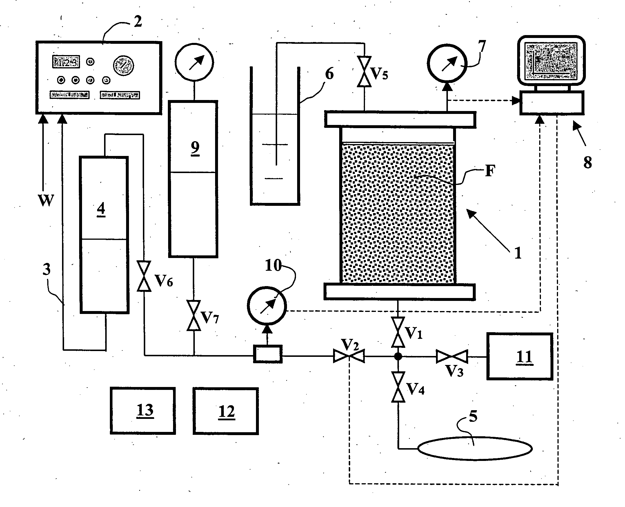
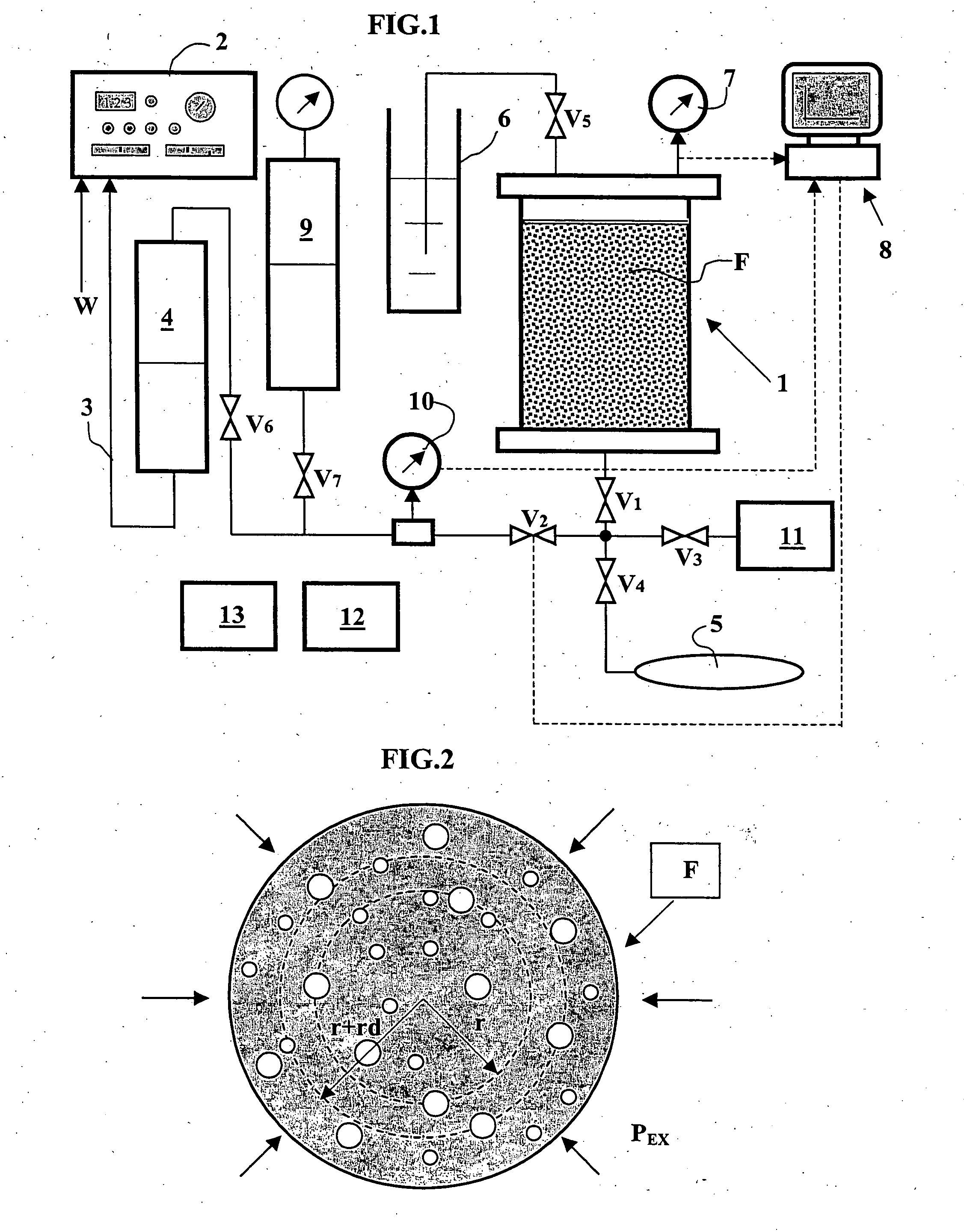
[0043] The device diagrammatically shown in FIG. 1 comprises a containment chamber 1 in which the drilling cuttings are initially placed. A constant-feed water pump 2 communicates through a line 3 with the base of a surge tank 4 containing a high-viscosity oil. The opposite end of surge tank 4 communicates through a valve V6 with a line L1. A first end of containment chamber 1 communicates with line L1 through the agency of two valves V1, V2. The opposite end of containment chamber 1 communicates, by means of an isolating valve V5, with a separator 6. A manometer 7 is connected to the outlet of chamber 1. The pressure variations measured by manometer 7 are acquired by a processor 8 such as a microcomputer. Valve V2 is directly controlled by processor 8. Line L1 also communicates by means of a valve V7 with a surge tank 9 containing viscous oil placed under a predetermined pressure by a gas cap under pressure. A flowmeter or a differential pressure detector 10 can be placed, if neces...


PUM

PropertyMeasurementUnit
flow rateaaaaaaaaaa
pressureaaaaaaaaaa
compressibilityaaaaaaaaaa

Abstract

Method and device for evaluating simultaneously, with the same equipment, physical parameters such as the absolute permeability and the porosity of fragments taken from a fragmented natural or artificial porous medium
The porosity of the fragments is measured by means of helium pressure tests according to a protocol known in the art. The chamber (1) containing the fragments is communicated with a tank (11) whose volume is also known and containing helium at a known pressure. At pressure balance, the value of the solid volume can be deduced. The rock envelope volume and the fragments mass are also measured. Combining these measurements allows to determine the porosity of the samples and the density of the rock. Their permeability is then measured by immersing them in a viscous fluid and by communicating the chamber with viscous fluid at a determined pressure contained in a vessel (9) so as to compress the gas trapped in the pores of the rock, according to two different protocols. The values of the physical parameters are determined by modelling the evolution of the pressure or of the volume in the chamber and by means of an iterative adjustment. Applications: petrophysical measurements from drilling cuttings or crushed cores for example.

Description

FIELD OF THE INVENTION [0001] The present invention relates to a method and to experimental devices for evaluating, with the same equipment and simultaneously, the porosity and the absolute permeability of any fragmented natural or artificial porous medium and notably of a zone of an underground reservoir containing hydrocarbons or other fluids, from rock samples taken from this medium. The samples can be, for example, fragments obtained during well drilling operations: drilling cuttings or fragments obtained by crushing bigger samples: cores or lateral cores taken in a well. [0002] The current petroleum context leads operators to take an interest in new zones (deep offshore) and in new reservoir types (marginal structures located close to existing surface installations). Considering the drilling costs linked with the difficult environment of these new discoveries or with the limited size of certain structures, operators can no longer afford to drill complementary appraisal wells wi...

Claims


Application Information

Patent Timeline
Patent Type & Authority Applications(United States)
IPC IPC(8): G01N15/08
CPCG01N15/0826G01N2015/0873G01N2015/0833G01N15/088
Inventor LENORMAND, ROLANDEGERMANN, PATRICKLONGERON, DANIEL
Owner INST FR DU PETROLE
Why Eureka
Try Eureka