Drive system and automobile

a technology of driving system and automobile, which is applied in the direction of engine starters, electrical control, hybrid vehicles, etc., can solve the problems of failure to re-start the engine, the accumulator that transmits electric power to and from the first motor may not have the marginal capacity to accumulate the electric power generated by the first motor, and the application of the first motor to stop the engine may be undesirable, etc., to achieve good startability and good startability of the internal combustion engin

Inactive Publication Date: 2005-08-18
TOYOTA JIDOSHA KK
View PDF1 Cites 42 Cited by
  • Summary
  • Abstract
  • Description
  • Claims
  • Application Information

AI Technical Summary

Benefits of technology

[0034] The control method of the second drive system of the invention has the magnetic field generation module that is arranged to generate a magnetic field of a preset magnetic polarity at a predetermined position of the crankshaft of the internal combustion engine toward an outer side of the crankshaft, and the position holding module that utilizes the magnetic force produced by the interaction with the magnetic field generated by the magnetic field generation module to hold the crankshaft of the internal combustion engine at the preset rotational position. This arrangement enables the crankshaft to be held at the preset rotational position at a stop of the internal combustion engine. The preset rotational position may be a position of ensuring good startability of the internal combustion engine. This ensures good startability when the internal combustion engine restarts.

Problems solved by technology

In the prior art drive system disclosed in Japanese Patent Laid-Open Gazette No. 2003-237392, application of the first motor to stop the engine may, however, be undesirable in some cases.
The accumulator that transmits electric power to and from the first motor may, however, not have the marginal capacity to accumulate the electric power generated by the first motor.
This leads to a failure in braking the rotation of the engine.
There may thus be difficulty in using only the first motor to stop the engine accurately at the target stop position.

Method used


Image

  • Drive system and automobile
  • Drive system and automobile
  • Drive system and automobile

Examples


first embodiment

(1) First Embodiment

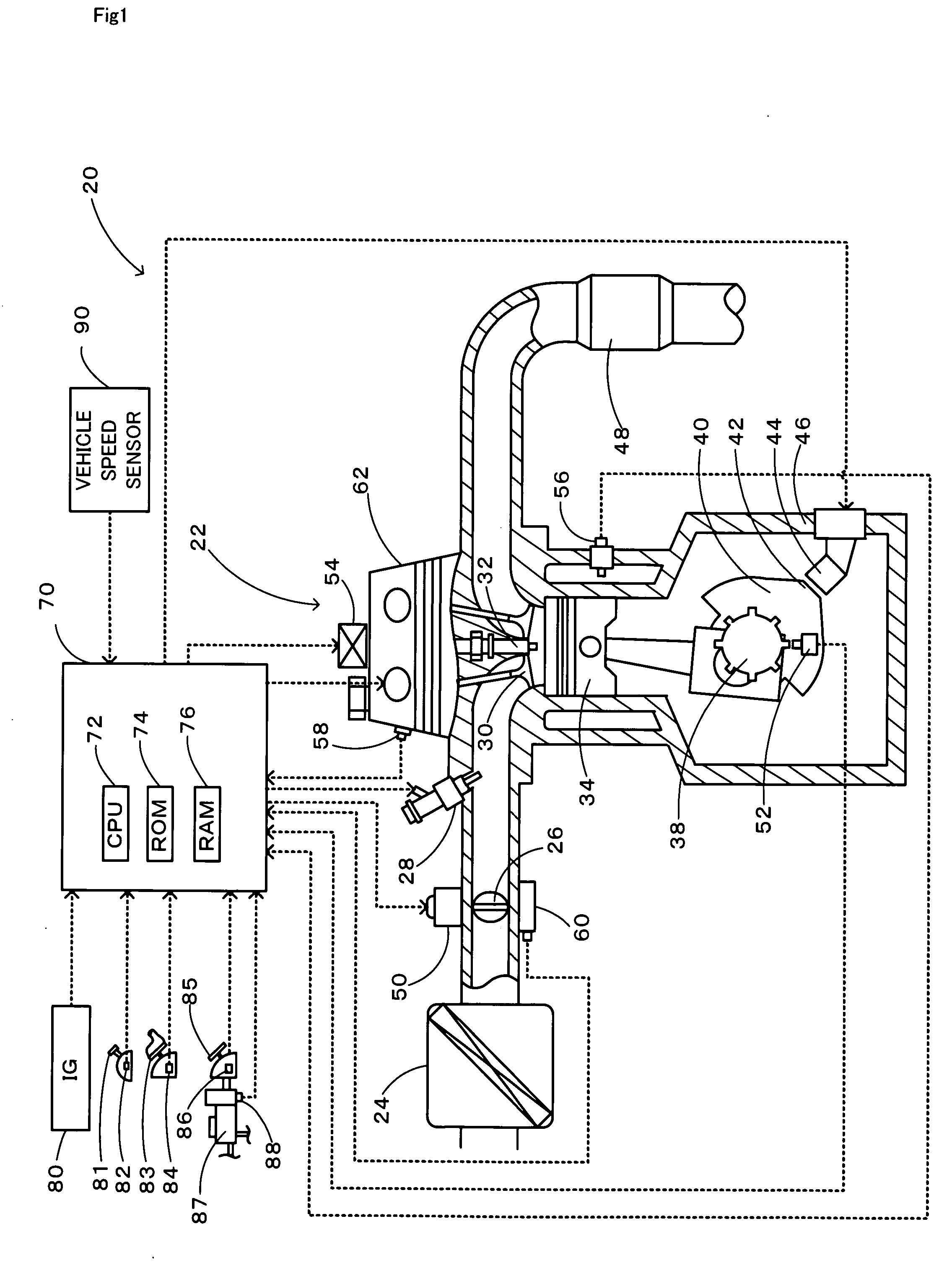
[0055]FIG. 1 schematically illustrates the structure of an engine system 20 constructed as a drive system including an internal combustion engine stop mechanism and an internal combustion engine auto stop start mechanism in a first embodiment of the invention. The engine system 20 of the first embodiment is mounted on an automobile and has an engine 22 as a power source and a controller 70 for controlling the operations of the engine 22.

[0056] The engine 22 is an internal combustion engine that consumes a supply of a hydrocarbon fuel, such as gasoline or light oil, to output power. In the engine 22, a supply of the air cleaned by an air cleaner 24 and taken by means of a throttle valve 26 is mixed with a supply of gasoline injected via a fuel injection valve 28 to an air-fuel mixture. The air-fuel mixture is taken into a combustion chamber via an intake valve 30 and is explosively ignited for combustion with an electric spark made by a spark plug 32. The combust...

second embodiment

(2) Second Embodiment

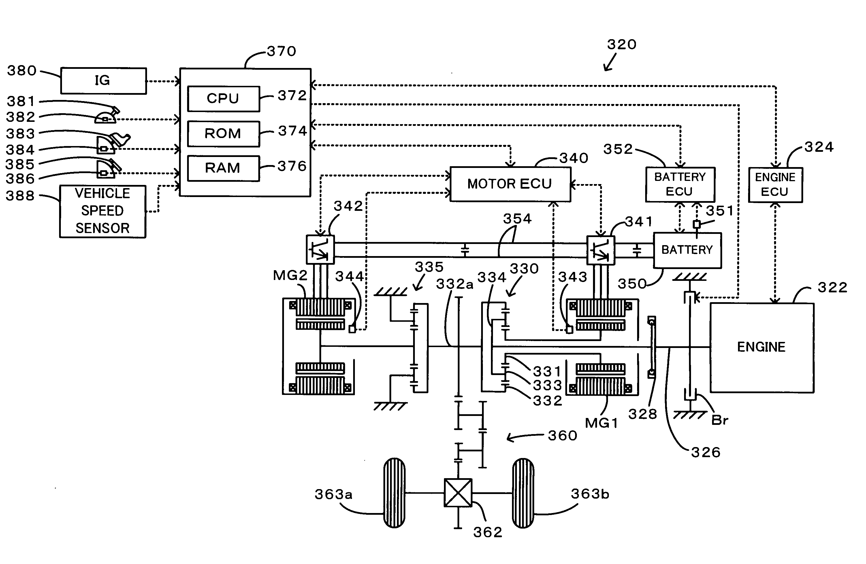
[0066] A second embodiment of the invention regards an engine system 20B constructed as a drive system including an internal combustion engine stop mechanism and an internal combustion engine auto stop start mechanism. The engine system 20B of the second embodiment has a similar structure to that of the engine system 20 of the first embodiment shown in FIG. 1, except some differences. The engine system 20B of the second embodiment additionally has a holder mechanism 100 that is mounted on the crankshaft 38 and turns and holds the crankshaft 38 to a specific rotational position of ensuring good startability of the engine 22 after a full stop of the engine 22 and a resulting full stop of the crankshaft 38, while omitting the projection 42 formed on the counterweight 40 attached to the crankshaft 38 and the electromagnet 44 attached to the crank casing 46 from the structure of the first embodiment. The like elements in the engine system 20B of the second embodiment...

third embodiment

(3) Third Embodiment

[0078] A third embodiment of the invention regards an engine system 20C constructed as a drive system including an internal combustion engine stop mechanism and an internal combustion engine auto stop start mechanism. FIG. 8 schematically illustrates the structure of a crankshaft 238 and a crank casing 246 included in the engine system 20C of the third embodiment. As illustrated, the engine system 20C of the third embodiment includes a permanent magnet 240 attached to the crankshaft 238, as well as three arc-shaped (about 90 degrees) permanent magnets 252, 254, and 256 set on the inner wall of the crank casing 246. The permanent magnet 252 is arranged to be aligned with and face the permanent magnet 240 attached to the crankshaft 238 when the crankshaft 238 is located at a specific rotational position of ensuring good startability of the engine 22. The permanent magnet 252 is magnetized to have magnetic polarity ‘S’ on its one side facing the crankshaft 238, whil...


PUM


Abstract

A counterweight 40 attached to a crankshaft 38 has a projection 42, which is aligned with and faces an electromagnet 44 attached to a crank casing 46 when the crankshaft 38 is at a preset rotational position of ensuring good startability of an engine 22. Engine stop control starts a power supply to the electromagnet 44 to attract the projection 42 of the counterweight 40 at a timing when the projection 42 of the counterweight 40 is practically aligned with the electromagnet 44, on the condition that the revolution speed of the crankshaft 38 is lowered to or below a preset level immediately before a full stop of rotation of the crankshaft 38. This engine stop control stops the rotation of the crankshaft 38 and desirably holds the crankshaft 38 at the preset rotational position of ensuring good startability of the engine 22.

Description

BACKGROUND OF THE INVENTION [0001] 1. Field of the Invention [0002] The present invention relates to a drive system and an automobile with the drive system mounted thereon, as well as a control method of the drive system. [0003] 2. Description of the Prior Art [0004] One proposed drive system includes a magnet generator having a flywheel linked to a crankshaft as a rotor and an armature arranged in the inner bore of the flywheel (see, for example, Japanese Patent Laid-Open Gazette No. 2001-193540). This proposed drive system adjusts the short circuit current supplied to the armature coil to regulate a braking torque applied to a crankshaft. The regulation of the braking torque sets the stop position of the crankshaft in a target range and thereby enhances the startability of an internal combustion engine. [0005] Another proposed drive system includes a first motor, an engine, and a drive shaft respectively connected with a sun gear, a carrier, and a ring gear of a planetary gear mec...

Claims


Application Information

Patent Timeline
Patent Type & Authority Applications(United States)
IPC IPC(8): B60K6/445B60W10/06F02D17/02F02D41/04F02N99/00
CPCB60K6/445B60W10/06B60W2510/0685F02D41/042F02D2200/1004Y02T10/6239F02D2200/602F02N11/0818F02N19/005F02N2019/008Y02T10/48F02D2200/501Y02T10/40Y02T10/62
Inventor YAMAUCHI, TOMOKAZUTAKI, NOBUYUKI
Owner TOYOTA JIDOSHA KK
Why Eureka
Try Eureka