Method and systems for controlling current in electrochemical processing of microelectronic workpieces

Inactive Publication Date: 2005-08-18
WILSON GREGORY J +2
View PDF0 Cites 24 Cited by
  • Summary
  • Abstract
  • Description
  • Claims
  • Application Information

AI Technical Summary

Benefits of technology

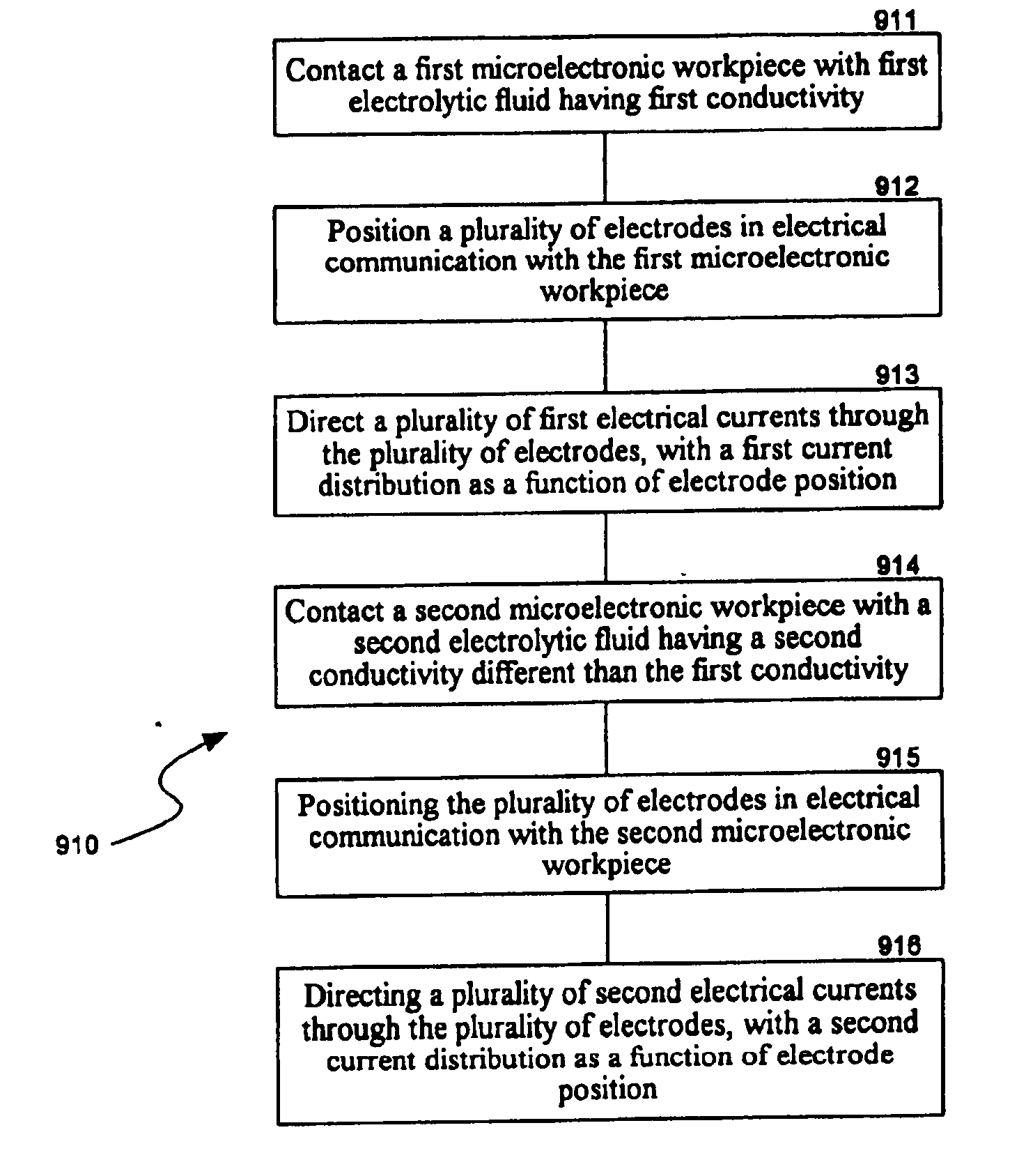
[0010] The present invention is directed toward methods and systems for electrolytically processing microelectronic workpieces. One aspect of several embodiments of the invention includes electrolytically depositing conductive material on a microelectronic workpiece by applying current to the workpiece through an electrolytic fluid from one or more electrodes. The distribution of current in the electrolytic fluid is actively changed during the course of the process. For example, in one embodiment, the current is applied by a plurality of electrodes in a manner that can account for different plating characteristics at different portions of the workpiece, and the current applied to individual electrodes is changed t

Problems solved by technology

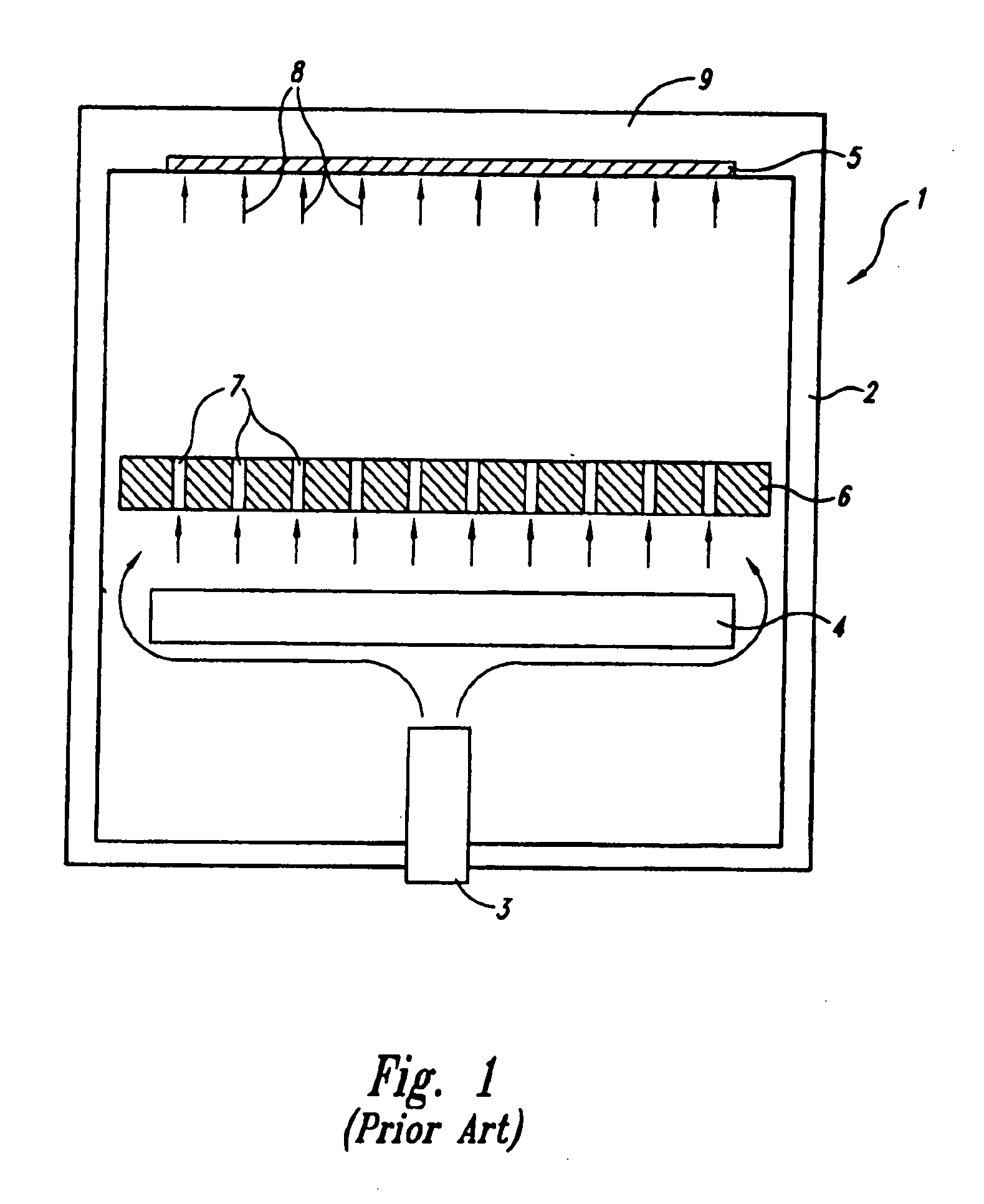
Although many different configurations of apertures have been used in plate-type diffusers, these diffusers may not provide adequate uniformity for the precision required in many current applications.
As a result, gas bubbles and/or particles can flow to the surface of the workpiece 5, which disrupts the uniformity and affects the quality of the plated layer.
Still another challenge of plating uniform layers is providing a desired electrical field at the surface of the workpiece 5.
Therefore, it can be difficult to maintain a desired current density at the surface of the workpiece 5 and can acc

Method used


Image

  • Method and systems for controlling current in electrochemical processing of microelectronic workpieces
  • Method and systems for controlling current in electrochemical processing of microelectronic workpieces
  • Method and systems for controlling current in electrochemical processing of microelectronic workpieces

Examples


Embodiment Construction

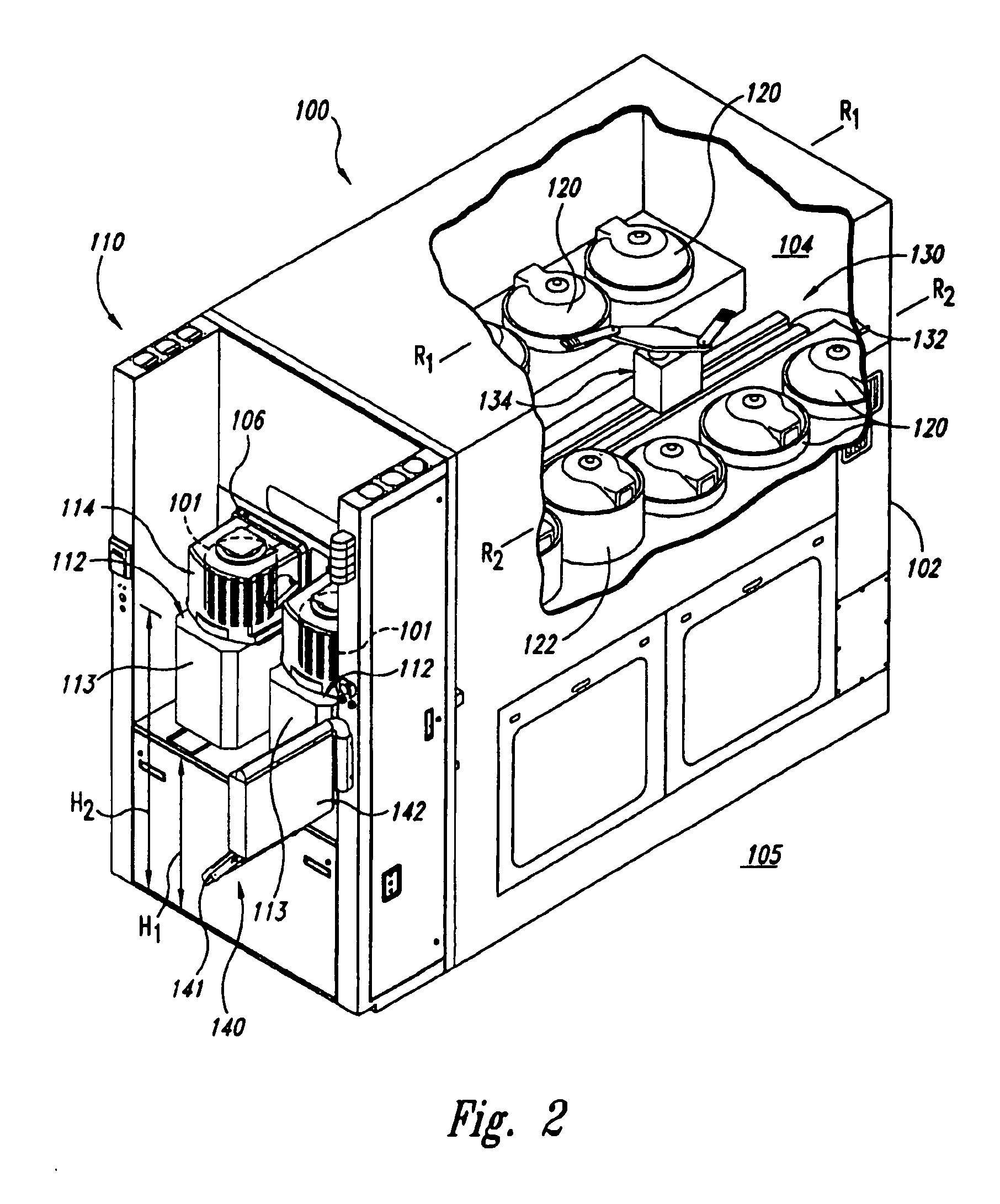
[0031] The following description discloses the details and features of several embodiments of electrochemical reaction vessels for use in electrochemical processing stations and integrated tools to process microelectronic workpieces. The term “microelectronic workpiece” is used throughout to include a workpiece formed from a substrate upon which and / or in which microelectronic circuits or components, data storage elements or layers, and / or micro-mechanical elements are fabricated. It will be appreciated that several of the details set forth below are provided to describe the following embodiments in a manner sufficient to enable a person skilled in the art to make and use the disclosed embodiments. Several of the details and advantages described below, however, may not be necessary to practice certain embodiments of the invention. Additionally, the invention can also include additional embodiments that are within the scope of the claims, but are not described in detail with respect ...


PUM

PropertyMeasurementUnit
Fractionaaaaaaaaaa
Fractionaaaaaaaaaa
Fractionaaaaaaaaaa

Abstract

A method and system for electrolytically processing a microelectronic workpiece. In one embodiment, the method includes contacting the workpiece with an electrolytic fluid, positioning one or more electrodes in electrical communication with the workpiece, directing an electrical current through the electrolytic fluid from the electrodes to the workpiece or vice versa, and actively changing a distribution of the current at the workpiece during the process. For example, the current can be changed such that a current ratio of at least one electrical current to the sum of the electrical currents shifts from a first current ratio value to a second current ratio value. Accordingly, the current applied to the workpiece can be adjusted to achieve a target shape for a conductive layer on the workpiece, or to account for temporally and/or spatially varying characteristics of the electrolytic process.

Description

CROSS-REFERENCE TO RELATED APPLICATIONS [0001] The present application claims priority to Provisional Application No. 60 / 294,690, filed May 30, 2001, which is incorporated herein in its entirety by reference.TECHNICAL FIELD [0002] This application relates to methods and systems for enhancing the performance of plating and other electrochemical processes. BACKGROUND [0003] Microelectronic devices, such as semiconductor devices and field emission displays, are generally fabricated on and / or in microelectronic workpieces using several different types of machines (“tools”). Many such processing machines have a single processing station that performs one or more procedures on the workpieces. Other processing machines have a plurality of processing stations that perform a series of different procedures on individual workpieces or batches of workpieces. In a typical fabrication process, one or more layers of conductive materials are formed on the workpieces during deposition stages. The wo...

Claims


Application Information

Patent Timeline
IPC IPC(8): C25D5/18C25D7/12C25D17/10
CPCC25D5/18C25D17/001C25D7/123C25D17/10C25D17/008C25D5/611
Inventor WILSON, GREGORY J.GIBBONS, KENNETHMCHUGH, PAUL R.
Owner WILSON GREGORY J
Why Eureka
Try Eureka