Compliant brush shroud assembly for gas turbine engine compressors

a gas turbine engine and compressor technology, applied in the direction of leakage prevention, air transportation, jet propulsion plants, etc., can solve the problems of reducing the compressor performance, reducing the maintenance cost, degrading the compressor performance, etc., and achieves the effects of easy maintenance, low cost, and easy manufacturing

Inactive Publication Date: 2005-08-18
ADVANCED COMPONENTS & MATERIALS
View PDF42 Cites 12 Cited by
  • Summary
  • Abstract
  • Description
  • Claims
  • Application Information

AI Technical Summary

Benefits of technology

[0008] One object of the present invention is to provide a brush shroud assembly which is inexpensive and easy to manufacture, relatively light weight, and which can be readily replaced, as needed.
[0009] There is provided herein a compliant brush shroud assembly for reducing the tip clearance between a rotating blade and the engine casing and which improves compressor performance. The brush shroud assembly includes a plurality of bristle packs supported within a housing such that the bristle distribution at the free ends, or inner diameter, of the bristle packs is continuous (i.e. there are no significant gaps between adjacent bristle packs.) The continuous surface is created by mounting the bristles packs within a housing such that the packs are flared, i.e. the width (axial length) at the outer diameter of the bristle pack is smaller than the width at the inner diameter.
[0010] In one embodiment, the compliant brush shroud assembly having a flared configuration and continuous inner diameter is fabricated by using one or more annular shroud rings which are supported within the housing. Each shroud ring preferably has a U-shaped configuration and may be welded or otherwise joined to a flexible bristle strip fabricated by attaching a plurality of bristle packs to one or more flexible rails. In a second embodiment, the annular ring is eliminated and the flexible bristle strips are secured directly to the housing, through one or more grooves or channels disposed in the housing. In a third embodiment, the flared configuration and continuous inner diameter is achieved by mounting the bristles packs within a holding ring having a plurality of holes to form a “tufted” ring. In a fourth embodiment, any of the first three embodiments (annular shroud ring, insert, and tufted) are utilized in combination with a rigid shroud ring supporting an abradable seal to form a hybrid assembly. In a fifth embodiment, the bristle angles are minimized from about 1-25 degrees in order to minimize bristle and blade damage due to bristle “suck down.” In any of the embodiments, the bristle pack may be mounted between a pair of crimped rails.
[0011] Once installed, all of the illustrative embodiments significantly reduce the clearance between the rotating blade and the engine casing as compared with conventional designs. The modular manner in which the bristles are mounted allows the bristles to be readily replaced, as needed. This can reduce both the labor cost and the cost due to lost service. In addition, by eliminating traditional back and front plates utilized with conventional brush seals, the weight of the above embodiments is reduced as compared to conventional brush seals.

Problems solved by technology

However, during a short-duration rub, the clearance is further enlarged, permanently reducing the compressor performance, such as its efficiency and stall margin.
Conventional rigid shroud casings degrade compressor performance as the abradable seal wears away, and also increases the maintenance cost due to frequent engine overhaul and lost service.
The lack of a continuous surface can result in the creation of vortices within the region, thus lowering the compressor efficiency.
Another important drawback of the CARL design is that the use of redundant front and back plates significantly increased the weight and cost of the system, which is particularly undesirable in aerospace applications where weight and cost reduction is important.
In addition, welding the bristles to the front and back plates can also lead to increased cost, both initially and later, during repairs.
In addition, if the rigid shroud ring is contacted by the rotor blade, it can damage both the blade and the shroud ring.
Once installed, all of the illustrative embodiments significantly reduce the clearance between the rotating blade and the engine casing as compared with conventional designs.

Method used


Image

  • Compliant brush shroud assembly for gas turbine engine compressors
  • Compliant brush shroud assembly for gas turbine engine compressors
  • Compliant brush shroud assembly for gas turbine engine compressors

Examples


example 1

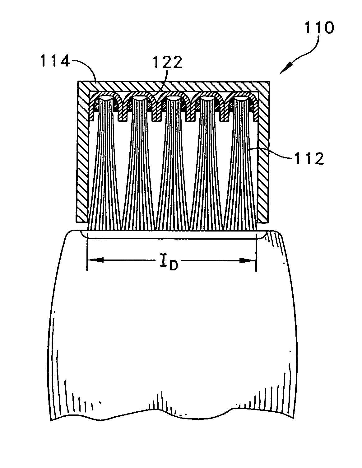
[0039] Low speed incursion tests were conducted with a variety of both flared and unflared bristle strips. Also, several samples were fabricated with a low bristle angle of about 10°, to minimize the interference of the bristles with the rotating blade tips. The bristle interference proportional to l(1−Cos θ), where l is the bristle length and θ bristle angle. By lowering the angle, the bristle pack radial stiffness was also increased. In the extreme case of 0° bristle angle, there will be no ‘bristle suck down’. However, bristle pack may tend to buckle instead of bending and increase the severity of the impact damage.

TABLE 1Bristle Characteristics of Low Speed Incursion TestsFlared (F)Estimated RadialUnflaredStiffnessSample #Bristle AngleBristle Density(U)Psi / mil145°1500 / inchU.33245°1500 / inchF.33335°1300 / inchU.54435°1300 / inchF.54525°1100 / inchU1.35625°1100 / inchF1.35710°1100 / inchF10.88810°1500 / inchF13.99

[0040] The ID of the samples was ED machined to 11″, same as the rotor OD. Duri...


PUM


Abstract

A brush shroud assembly for reducing the tip clearance between a rotating blade and an engine casing is disclosed. The assembly includes a plurality of bristle packs supported within a housing such that the bristle distribution at the inner diameter of the bristle packs is substantially continuous. The continuous surface is created by mounting the bristles packs within a housing such that the packs are flared, i.e. width at the outer diameter of the bristle pack is smaller than that at the inner diameter. Various embodiments are disclosed for mounting the flared bristle packs to form a substantially continuous inner diameter. The bristle strips may be mounted in one or more annular rings, may be secured within one or more channels in the housing, the bristle packs may be formed into a tufted ring, or any of these may be utilized in combination with a backplate supporting an abradable seal, i.e. a hybrid design.

Description

CROSS REFERENCES TO RELATED APPLICATIONS [0001] The present application is a continuation under 37 CFR § 153(b) of co-pending U.S. patent application Ser. No. 10 / 397,060, filed Mar. 25, 2003 which was a continuation-in-part of U.S. patent application Ser. No. 10 / 012,979, filed Nov. 5, 2001, and issued as U.S. Pat. No. 6,536,773 on Mar. 25, 2003, which claimed priority under 35 USC § 119(e) to U.S. Provisional Patent Application Ser. No. 60 / 246,182, filed on Nov. 6, 2000. The entire contents of the above applications are incorporated herein by reference in entirety.TECHNICAL FIELD [0002] The invention relates generally to a brush shroud assembly for sealing a gap between an engine casing and rotating blade, and, more specifically, to a brush shroud assembly including a bristle strip having a plurality of bristles mounted in a compliant casing such that the bristles are flared to form a continuous surface to seal a blade-tip flow area, the bristles also having an angle with respect to...

Claims


Application Information

Patent Timeline
Patent Type & Authority Applications(United States)
IPC IPC(8): F01D11/08F01D11/12F02C7/28F16J15/32
CPCF01D11/08F01D11/127F05D2240/56F16J15/3288Y02T50/671F02C7/28F04D29/164Y02T50/60
Inventor DATTA, AMITAVA
Owner ADVANCED COMPONENTS & MATERIALS
Why Eureka
Try Eureka