Fiber optic damage detection system for composite pressure vessels

a composite pressure vessel and fiber optic technology, applied in optical radiation measurement, transmission monitoring, instruments, etc., can solve the problems of reduced strength of composite structures, relatively susceptible to shock and impact damage, and broken fibers, and achieve the effect of low cos

Active Publication Date: 2005-08-18
THE BOEING CO
View PDF1 Cites 26 Cited by
  • Summary
  • Abstract
  • Description
  • Claims
  • Application Information

AI Technical Summary

Benefits of technology

[0010] In accordance with the present invention, a reliable, low cost apparatus and method of use are provided for detecting structural damage incurred by a filament wound composite pressure vessel. In one advantageous embodiment, the damage detector comprises an optical fiber wound onto an exterior surface of the composite structure and adhered thereto with an adhesive. The core of the optical fiber may be silica, to approximate the tensile strength and frangibility of the filaments of the underlying composite structure. Advantageously, the optical fiber may be wound onto the underlying structure while wetted with a coating of a liquid epoxy resin, and the resin then cured to adhere the fiber to the structure. The optical fiber is preferably wound on the composite structure in a regular, two-dimensional pattern in which adjacent windings are spaced at a selected distance from each other, and in which points along the length of the fiber are mapped onto specific, known locations on the surface of the underlying structure. The winding pattern may comprise either helical or axial windings, or both.

Problems solved by technology

Features common to all composite pressure vessels used in aerospace applications are their relatively thin structural walls and thin metallic or elastomeric liners, which are used to minimize weight, and which render them relatively susceptible to shock and impact damage.
Surface impact events experienced by these structures can cause significant local deflections resulting in broken fibers.
The reduction in strength of the composite structure resulting from broken fibers can have implications that range from the need for relatively low-cost repairs, to a catastrophic failure of the vessel that can lead to calamitous failure of a flight vehicle.
Unfortunately, not all impact events that occur subsequent to production inspection and that result in broken fibers are visually observed and reported through appropriate channels so that a detailed inspection is initiated to evaluate vessel integrity.
However, for some high performance composite structures that are weight critical, such measures are not feasible, and multiple inspections are therefore necessary to ensure structural integrity.
Accordingly, some space vehicle programs may expend very large sums of money each year to re-inspect solid rocket motor cases for impact damage using traditional non-destructive inspection methods prior to launch.
Because of these high costs, new apparatus and methods for detecting impact or handling damage in composite structures are needed.
The drawback of these structures lies in the embedding within them of fiber optic sensors, which are typically larger than the adjacent structural ply fibers, and which therefore can adversely affect the strength of the lay-up or sustain embedded fiber damage during the curing process.

Method used


Image

  • Fiber optic damage detection system for composite pressure vessels
  • Fiber optic damage detection system for composite pressure vessels
  • Fiber optic damage detection system for composite pressure vessels

Examples


Embodiment Construction

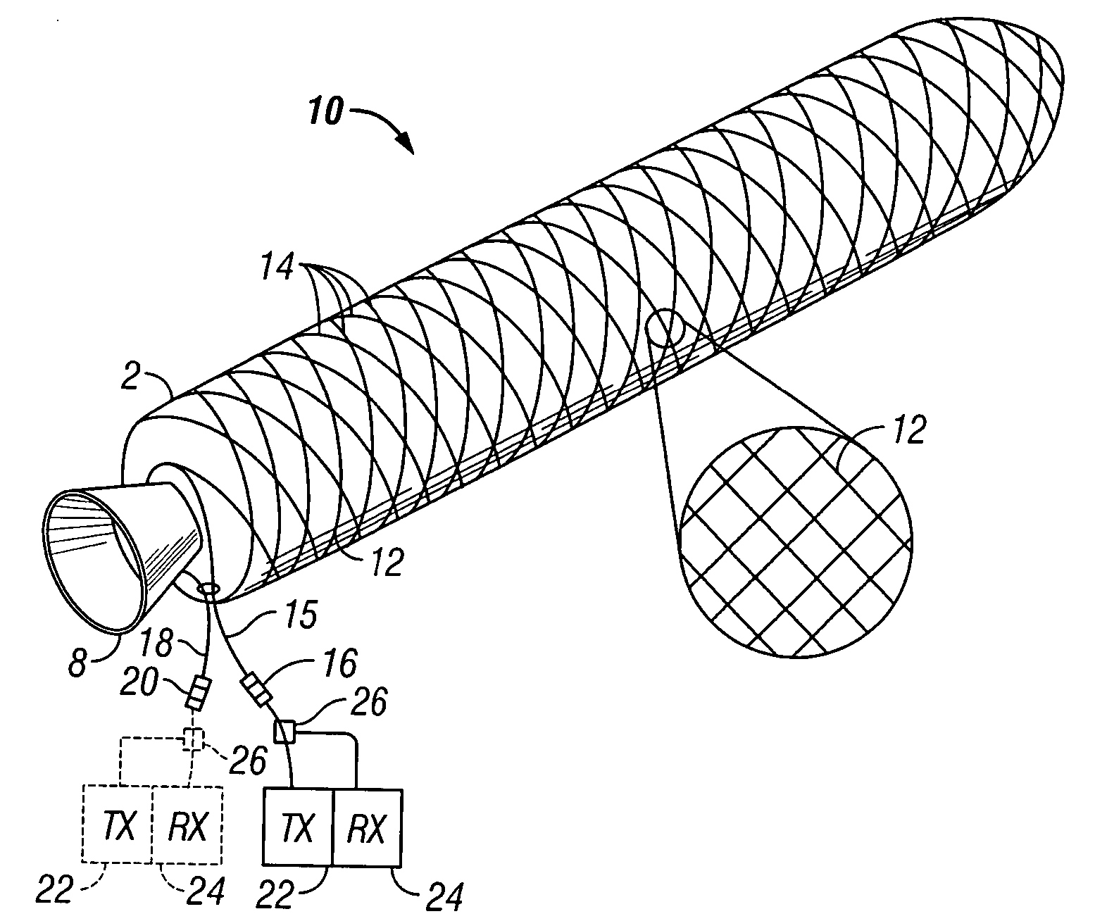
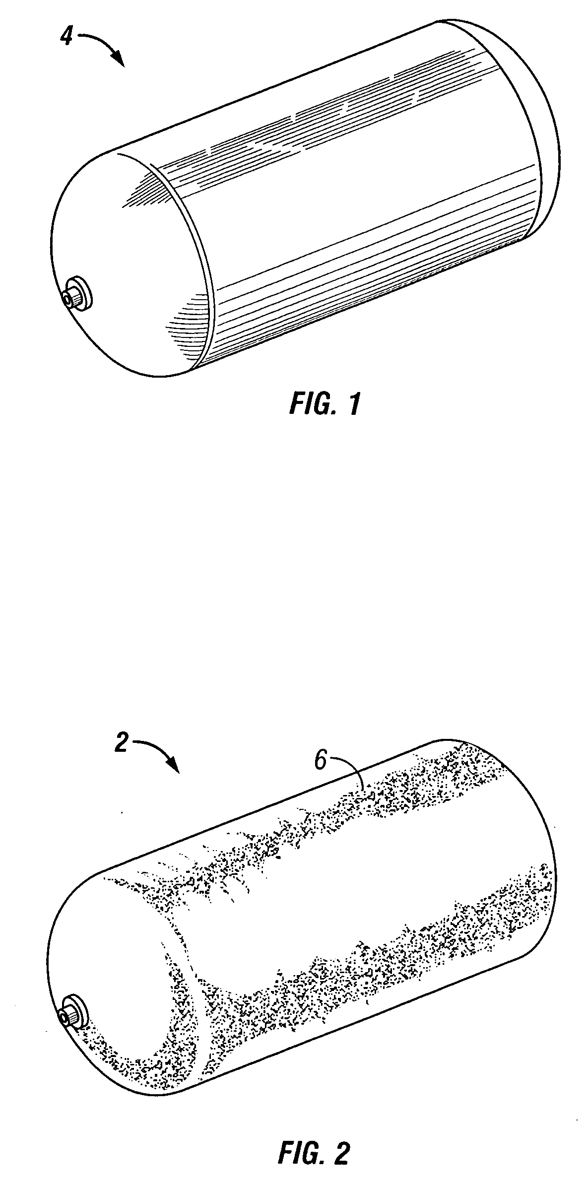
[0021] A filament-wound composite structure 2, viz., a composite overwrapped pressure vessel, or COPV, to which the present invention has advantageous application, is illustrated in the perspective view of FIG. 2. The particular composite pressure vessel illustrated comprises a liquid propellant tank, and includes a hollow, generally cylindrical, polymeric or metallic, e.g., plastic, titanium, aluminum or stainless steel, inner liner 4, such as that illustrated in FIG. 1. While the liner is shown as cylindrical in shape, it should be understood that such a liner may have many other shapes, including, e.g., oblate spheroids, “near spheres,” or spheres. The underlying mandrel for the composite pressure vessel could also be a solid propellant casting or a mechanically removable or dissolvable structure (e.g., salt or plaster) that is not an integral component of the final pressure vessel.

[0022] The exterior surface of the liner 4 may be densely over-wound in a helical and / or longitudi...


PUM


Abstract

An optical fiber is wound onto an exterior surface of a composite structure, such as a composite overwrapped pressure vessel (“COPV”), in a two-dimensional pattern and adhered thereto, e.g., with a resin, to detect damage to the structure caused by impacts to or handling of the structure. After fabrication of the structure, a signature, or baseline, reference signal is established by detecting a light signal transmitted through the length of the fiber. Later, after the structure has been transported, handled, or placed into service, a second signal similar to the first is sent through the fiber and compared with the reference signal. Changes detected in the signal indicate that the structure may have sustained structural damage that may be invisible to external visual inspection, but that can be detected by more costly and time consuming conventional non-destructive inspection methods. In another embodiment, a pulsed light signal reflecting from a discontinuity in the optical fiber can be used to determine the location of the damage.

Description

BACKGROUND OF THE INVENTION [0001] 1. Field of the Invention [0002] This invention relates to non-destructive testing methods and apparatus in general, and in particular, to the use of optical fibers as an indicator of damage to filament wound composite pressure vessels. [0003] 2. Related Art [0004] A number of important fiber reinforced composite structures are currently being manufactured using filament winding. They are made in a broad range of sizes, and are categorized primarily by their application. Aerospace applications include vessels for high-pressure gas containment, liquid propellant tanks, and solid rocket motors. Such vessels are also used extensively in non-Aerospace applications, but are normally designed to be much more robust, as weight control is typically not as critical. Currently, solid rocket motor cases of up to 5 feet in diameter are being made, and even larger sizes are possible. They typically have an elastomeric liner / insulator on the inside of the case w...

Claims


Application Information

Patent Timeline
Patent Type & Authority Applications(United States)
IPC IPC(8): G01M11/08G02B6/00
CPCG01M11/085
Inventor ANDREWS, THOMAS L.GRIMES-LEDESMA, LORIE R.
Owner THE BOEING CO
Why Eureka
Try Eureka