Optoelectronic hybrid integrated module and light input/output apparatus having the same as component

a hybrid integrated module and light input/output technology, applied in the direction of optical elements, semiconductor lasers, instruments, etc., can solve the problems of increasing limiting the capacity, increasing the mounting cost, etc., to reduce the number of components and processes, suppress the dispersion of light output, and reduce the mounting cost

Inactive Publication Date: 2005-08-18
NEC CORP
View PDF6 Cites 27 Cited by
  • Summary
  • Abstract
  • Description
  • Claims
  • Application Information

AI Technical Summary

Benefits of technology

[0020] As described above, the present invention has such a configuration that an optical device and an input / output IC are flip-chip mounted on a transparent base material, and by utilizing the light permeability of the transparent base material, light inputting / outputting to / from the optical device is carried out. Thereby, the number of components and processes can be reduced, so that the mounting cost is suppressed. Further, a narrow margin of wiring is acceptable, whereby the mounted components can be arranged in high density. Moreover, a low-cost plate, in which an electromagnetic shield is taken into account, can be realized, dispersions in light outputs can be suppressed, and sealing can be done relatively easily.

Problems solved by technology

In such a case, limitation of capacity, due to the distance of electrical connections or sizes in the large-capacity connections between cabinets or inside a cabinet, is concerned.
This causes a problem of an increase in the number of components and processes, and an increase in the mounting cost.
Further, in drawing out the wiring, a wider margin of the wiring is required for wire-bonding the optical device, which causes a problem that high-density mounting of the components becomes difficult.
Further, in order to carry out electromagnetic shielding effectively, the case is preferably made of metal such as covar, which causes a problem of an increase in the cost.
Further, in extracting or taking in lights, since the lens and the optical device are mounted separately, dispersion of the distance between the lens and the optical device or their positions becomes large, which causes a problem of dispersion of the optical outputs themselves.
Moreover, since the lens is fixed with an adhesive, hermetic sealing is also difficult.

Method used


Image

  • Optoelectronic hybrid integrated module and light input/output apparatus having the same as component
  • Optoelectronic hybrid integrated module and light input/output apparatus having the same as component
  • Optoelectronic hybrid integrated module and light input/output apparatus having the same as component

Examples


example

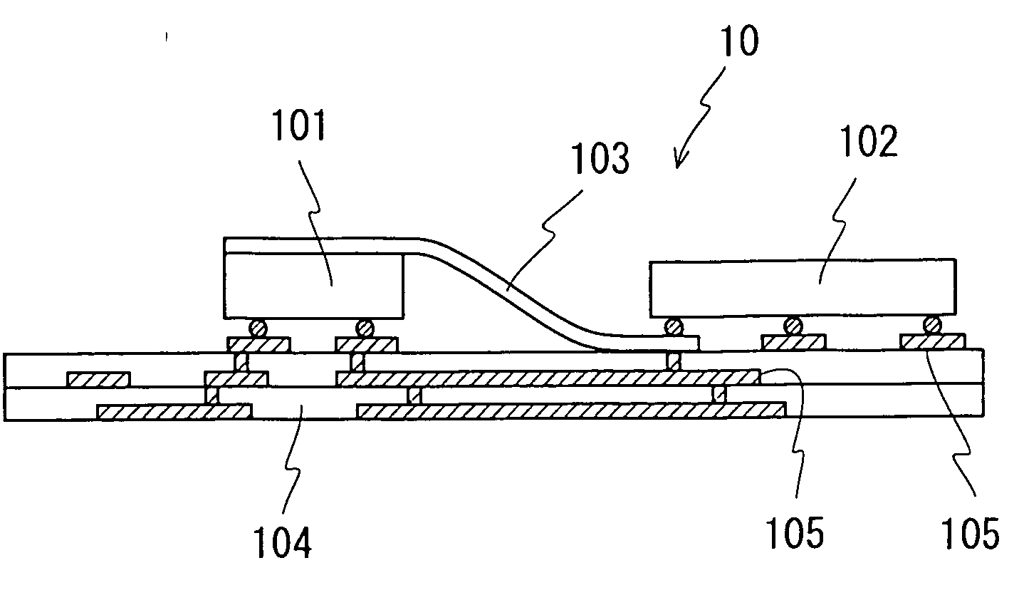
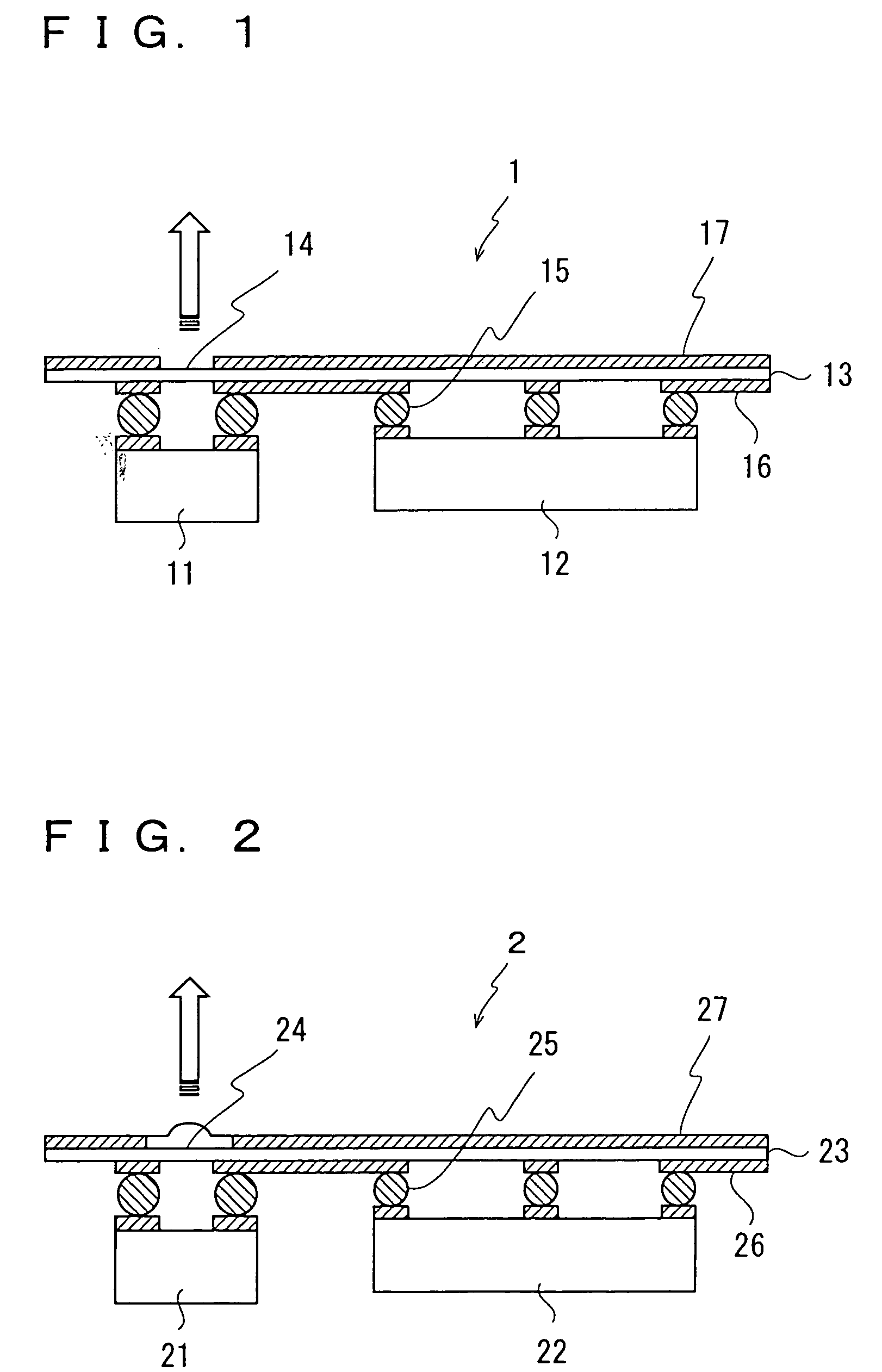
[0062] A specific example of the optoelectronic hybrid integrated module 1 shown in FIG. 1 will be described. The optical device 11 was a vertical cavity surface emitting laser (VCSEL) with an oscillation wavelength of 850 nm, and was flip-chip mounted on the transparent plate using AuSn solder as the metal bumps 15. As the transparent plate 13, one having high light permeability to the oscillation wavelength of 850 nm of the optical device 11 was selected. The driver IC 12 controlled input currents to the optical device 11 according to electric signals of 3.125 Gb / s differentially input from the outside. The amplitude of currents supplied to the optical device 11 was about several mA, and the maximum output was −1 dBm. Since the optical device 11 and the light extracting part 14 were flip-chip mounted, the coupling effect was −3±0.3 dB.


PUM


Abstract

On the back surface of a transparent plate having a light extracting part 14 for outputting lights to the outside, an electrode 16 for wiring, and an electrode 17 for an electromagnetic shield, an optical device 11 is flip-chip mounted right under the light extracting part 14, an a driver IC 12 is flip-chip mounted at a desired position with metal bumps 15. When currents driving the optical device 11 flow from the driver IC 12 according to an electric logical signal from the outside, an optical signal is emitted from the optical device 11, and is output to the outside through the light extracting part 14. The light extracting part 14 may be provided with a light coupling material or an optical axis converter.

Description

TECHNICAL FIELD [0001] The present invention relates to an optoelectronic hybrid integrated module, and in particular, to an optoelectronic hybrid integrated module in which an optical device, a driver IC and the like are mounted. BACKGROUND ART [0002] In recent years, large-scale switching systems such as large-capacity routers are required corresponding to an increase in the capacity of communication networks. In such a case, limitation of capacity, due to the distance of electrical connections or sizes in the large-capacity connections between cabinets or inside a cabinet, is concerned. This is because higher-speed and higher-density electric signal wiring and delays in electric wiring stand as bottlenecks in realizing higher performance, although operating speed and integration scale have been improved along with the developments in the IC and LSI techniques. As a technique to solve this problem, an optical interconnection is drawing the attention. As a configuration of a small ...

Claims


Application Information

Patent Timeline
Patent Type & Authority Applications(United States)
IPC IPC(8): H01L25/16H01L31/02H01L33/56H01L33/62H01S5/02
CPCH01L25/167H01S5/02248H01S5/02272H01S5/02288H01L24/73H01L2224/32225H01L2924/3011H01L2224/48227H01L2224/73265H01L2224/48091H01L2924/3025H01L2224/16225H01L2924/00014H01L2924/00H01L2224/05568H01L2224/05573H01L2924/12042H01L2924/14H01S5/183H01S5/02253H01S5/02325H01S5/0237H01L2224/05599
Inventor SHIMIZU, TAKANORISUGIMOTO, TAKARASASAKI, JUN-ICHIKURATA, KAZUHIKO
Owner NEC CORP
Why Eureka
Try Eureka