Apparatus and method for detecting vibrations of the shaft assembly in an electrical machine

a technology of shaft assembly and apparatus, which is applied in the field of apparatus and methods for detecting vibrations of shaft assemblies in electrical machines, can solve the problems of natural frequency of shaft assemblies, which are difficult to measure during operation, and are detected

Inactive Publication Date: 2005-08-25
GENERAL ELECTRIC TECH GMBH
View PDF13 Cites 23 Cited by
  • Summary
  • Abstract
  • Description
  • Claims
  • Application Information

AI Technical Summary

Benefits of technology

[0012] The shaft voltages and shaft currents may, however, also be used for monitoring the functional safety and functional reliability of the shaft grounding. The document mentioned initially EP-A1-0 271 678 specifies for this purpose a monitoring and evaluation circuit which provides a current path on the non-drive side of the generator by a resistor being connected in parallel with the dissipation capacitor, and evaluates machine-typical frequency components in the currents flowing through this RC combination. The RC combination provides a reliable connection between the shaft and ground potential, which reduces both static charges and higher-frequency voltages to levels which are unhazardous for the shaft bearing.
[0016] In accordance with a further preferred embodiment, the measurement of the shaft voltage and / or the shaft current takes place such that a low-resistance connection to ground is provided at a first point on the shaft, upstream of the generator, and such that, at a second point on the shaft, downstream of the generator, the shaft voltage, i.e. the voltage between the shaft and ground, and / or the shaft current, i.e. the current flowing to ground, is tapped off via a unit, for example a high-resistance RC unit between the shaft and ground, and analyzed in an analysis unit. In this case, for analysis of the shaft voltage and / or the shaft current, the signal is particularly preferably measured and recorded as a function of time and analyzed as a function of time. The sampling can in this case take place at a sampling rate which corresponds to the system frequency or to integral multiples of the system frequency divided by the number of pole pairs in the generator. The resulting signal (voltage or current) is preferably investigated as regards frequency modulations and / or amplitude modulations of the harmonics of the shaft voltage / current spectrum, which it contains. In this case, possibly after demodulation or down-mixing of the signal, sections are preferably subjected to a Fourier transformation at a carrier frequency, in particular at the system frequency or harmonics thereof, and the resulting spectrum is analyzed for instances of line broadening of the harmonics, in the case of frequency modulations, or for sidebands, or else bands in the baseband, in the case of amplitude modulations. This type of analysis allows for simple visualization of the corresponding signals which are characteristic of specific vibrations.

Problems solved by technology

In particular, the natural frequencies of the shaft assembly, which are difficult to measure during operation, are detected, in particular also their changes over the course of time.

Method used


Image

  • Apparatus and method for detecting vibrations of the shaft assembly in an electrical machine
  • Apparatus and method for detecting vibrations of the shaft assembly in an electrical machine

Examples


Embodiment Construction

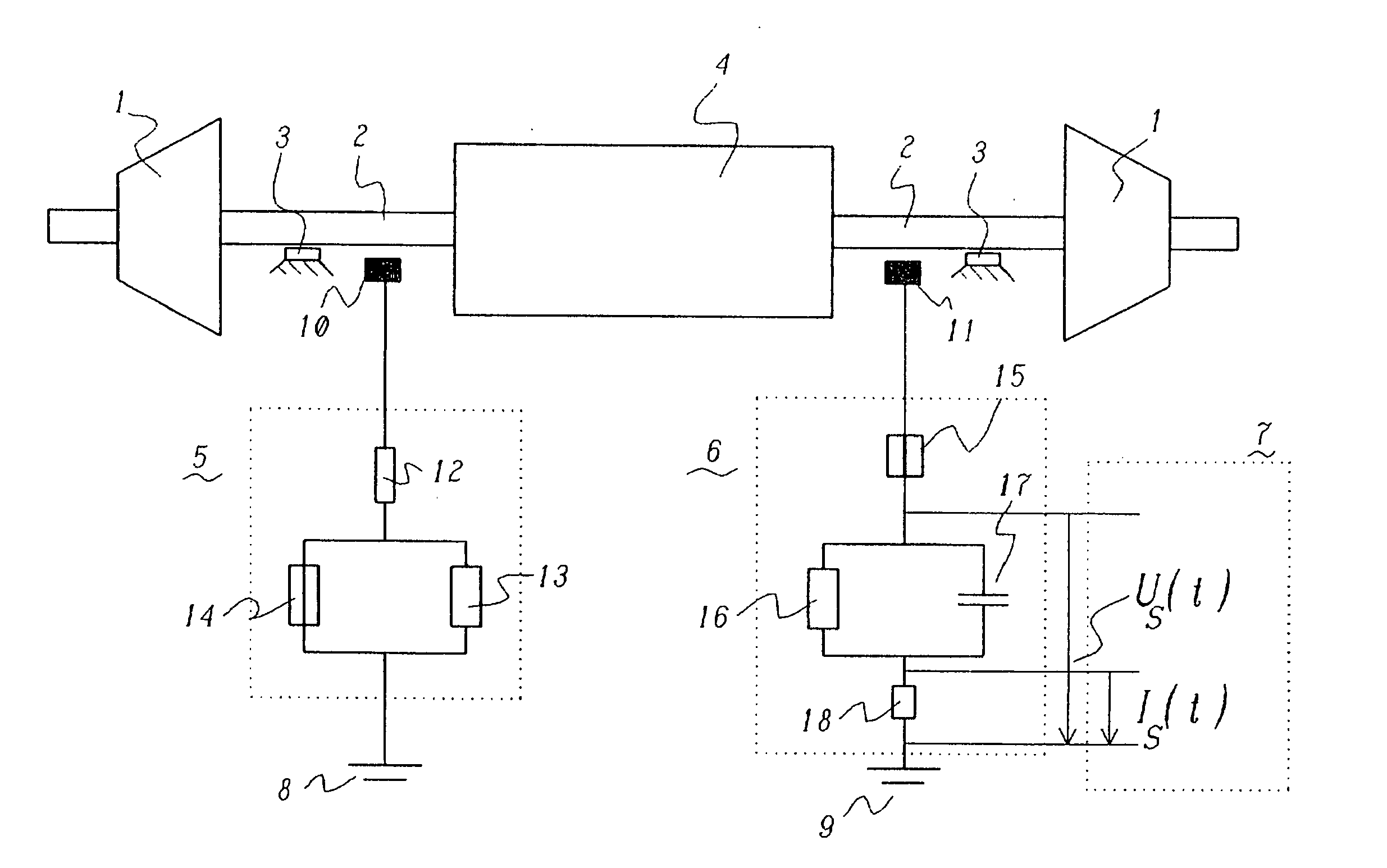
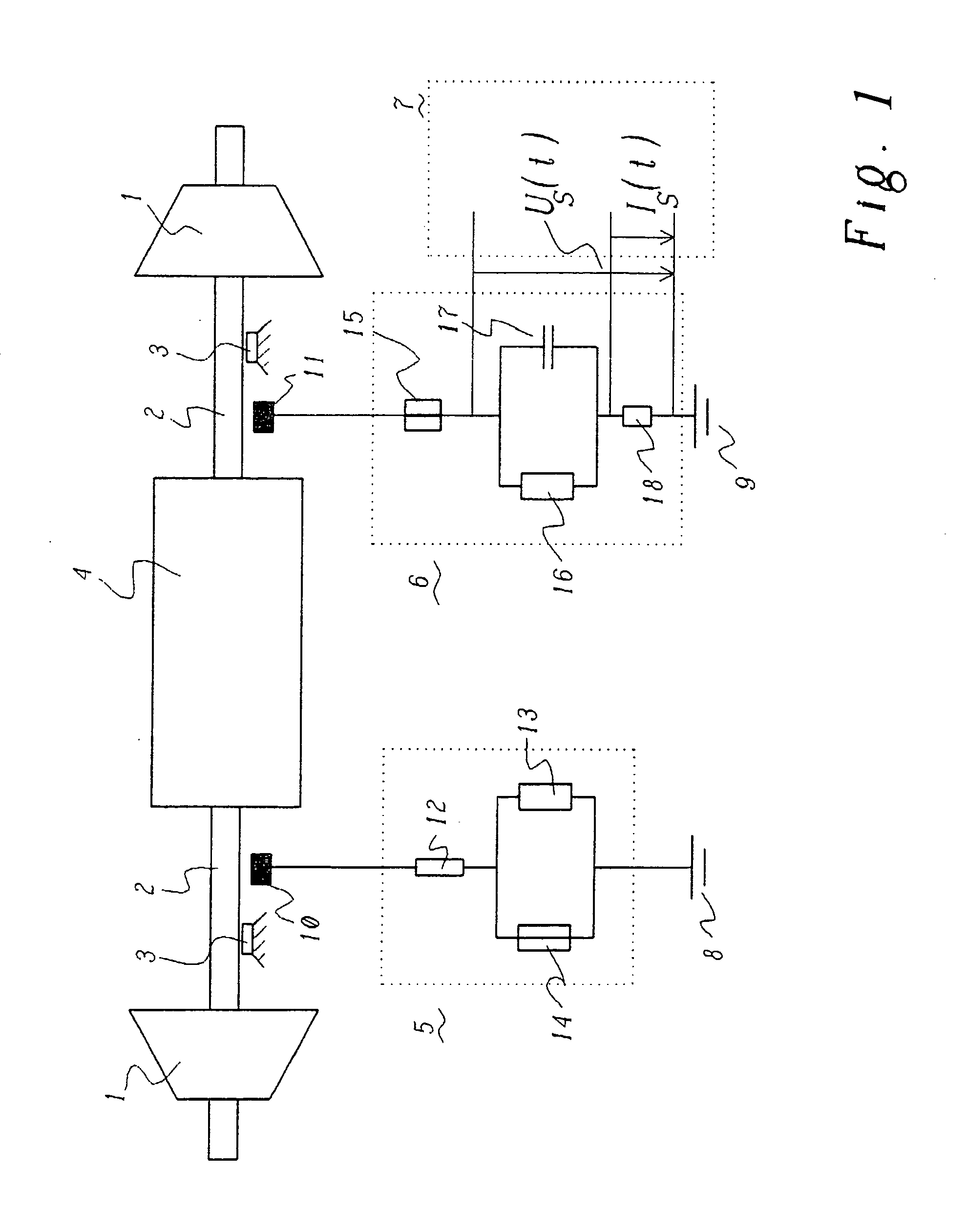
[0027] The FIG. 1 shows a schematic illustration of a gas turbine plant, in which two turbines 1 are arranged on either side of a generator 4, the two turbines 1 and the generator 4 being arranged on a common shaft 2 or a shaft assembly. The two turbines are in this case to be understood merely as an example; it is also possible for only one turbine to be arranged. In order to be able to disconnect the generator 4, for example when the turbines 1 are stepped up, couplings are generally provided which make it possible to mechanically decouple the turbines 1 from the generator 4.

[0028] The shaft 2 is mounted on at least two shaft bearings 3. The oil films present in the bearings 3 insulate the shaft 2 electrically from the bearings 3 which are connected to ground. This insulation may, however, fail at voltage peaks above a specific level, which may lead to problems with electric spark erosion.

[0029] As has already been mentioned initially, for various reasons shaft voltages and shaf...


PUM

PropertyMeasurementUnit
frequenciesaaaaaaaaaa
frequencyaaaaaaaaaa
frequencyaaaaaaaaaa

Abstract

A method for detecting vibrations of a shaft of an electrical machine includes measuring at least one of a shaft voltage and a shaft current and analyzing the measured at least one of the shaft voltage and the shaft current so as to determine the vibrations. In addition, an apparatus for detecting vibrations of a shaft of an electrical machine includes a first grounding device disposed at a first point on the shaft on a first side of the electrical machine and a second grounding device disposed at a second point of the shaft on a second side of the electrical machine. The second grounding device is configured to measure at least one of a shaft voltage and a shaft current.

Description

[0001] This patent application is a continuation for International Patent Application No. PCT / EP2003 / 50610, filed on Sep. 5, 2003, which claims priority to Swiss Patent Application No. CH 2002 1529 / 02, filed on Sep. 10, 2002. The entire disclosure of both applications is incorporated by reference herein.[0002] The present invention relates to a method and an apparatus for detecting vibrations of the shaft assembly in an electrical machine, in particular in power plants. BACKGROUND [0003] Vibrations of the shaft assembly of a machine, in particular of a turbo generator assembly, may be of a variety of types. They may be bending vibrations or transverse vibrations which occur in the direction perpendicular to the shaft. Furthermore, so-called oscillations may occur, i.e. generally changes in the rotational frequency of the shaft, which are damped quasi-periodically, about the system frequency of generally 50 Hz (or 60 Hz), which are generated by, for example, sudden disruptions to the...

Claims


Application Information

Patent Timeline
Patent Type & Authority Applications(United States)
IPC IPC(8): G01H1/00G01H17/00G01H1/10G01H11/06G01N29/00G01R31/34
CPCG01H1/006G01H1/003
Inventor HOBELSBERGER, MAXKIRCHHOFF, INGOPOSEDEL, ZLATIMIR
Owner GENERAL ELECTRIC TECH GMBH
Why Eureka
Try Eureka