
Display device integrated with solar cells and method of fabricating the same

Inactive Publication Date: 2005-08-25
SAMSUNG SDI CO LTD
View PDF6 Cites 27 Cited by
  • Summary
  • Abstract
  • Description
  • Claims
  • Application Information

AI Technical Summary

Benefits of technology

[0009] It is also an object of the present invention to provide a solar cell integrated display device where both the display and the solar cell can operate simultaneously.
[0015] These and other objects can be achieved by a solar cell integrated display device having an emissive display device unit that has a first transparent substrate, a first transparent electrode deposited on the transparent substrate, a second transparent electrode facing the first transparent electrode, and a light emitting layer between the first transparent electrode and the second transparent electrode. In addition, the solar cell integrated display device has a polymer membrane coated on the second transparent electrode, the polymer membrane having CNT (carbon nanotubes) mixed therein to allow for a smooth flow of electrons, and a solar cell unit that supplies power to the display device unit and stacked on the polymer membrane.

Problems solved by technology

However, since a display panel can only be viewed from one side, generated rays that travel towards the screen can be viewed while all other rays that do not travel towards the screen are not viewed and are thus wasted.
Such units are also bulky in volume as they consume a lot of space.
Further, they have lots of wiring making such devices complicated.
The wires generate noise which further disrupts operation of the device and other devices in the vicinity.

Method used


Image

  • Display device integrated with solar cells and method of fabricating the same
  • Display device integrated with solar cells and method of fabricating the same
  • Display device integrated with solar cells and method of fabricating the same

Examples


Embodiment Construction

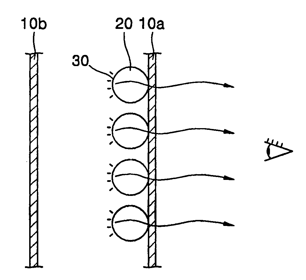
[0029] Emissive display devices are generally divided into transmission type and reflection type. The transmission type display device is a display device where light from a surface of the light emitting source material that is recognized by a human visual recognition system must travel through the light emitting source material.

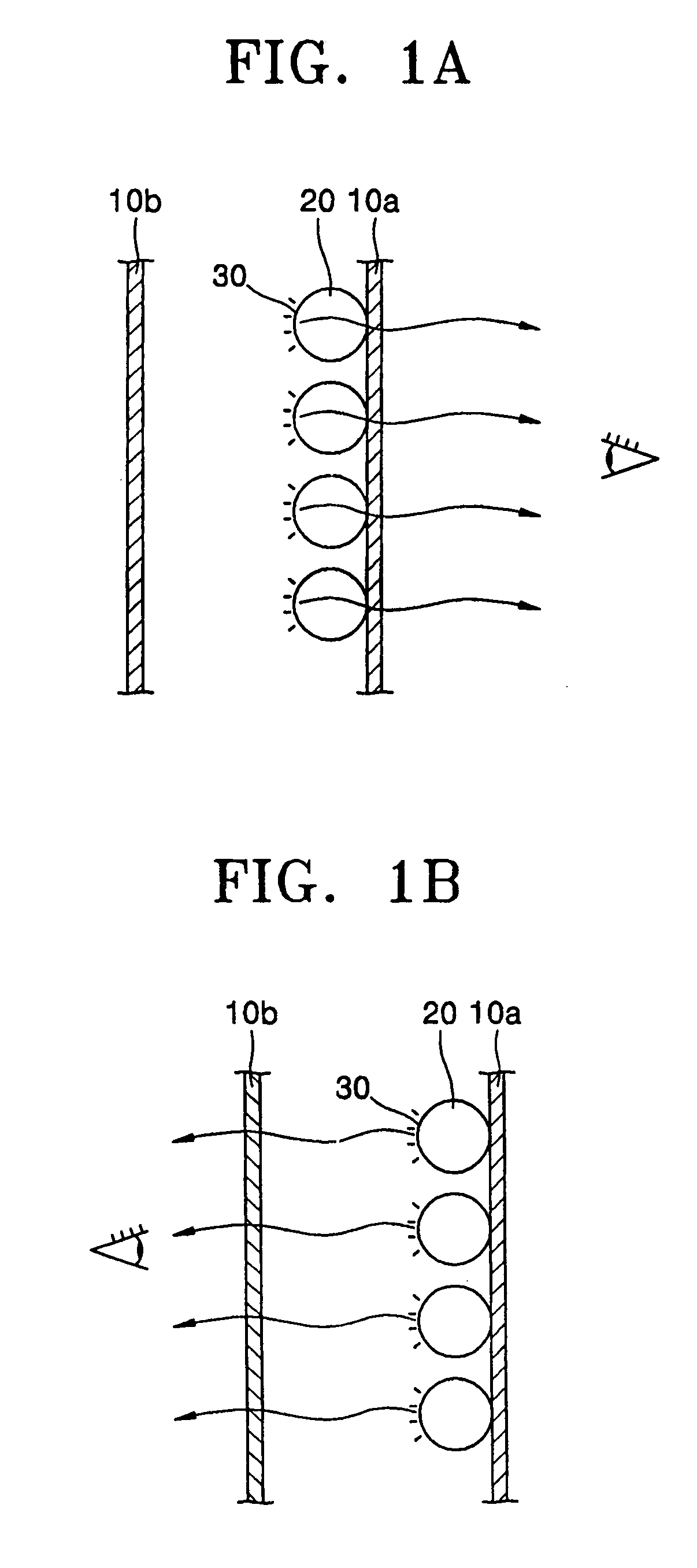
[0030] Turning now to the figures, FIG. 1A is a schematic drawing illustrating a transmission type display device. As depicted in FIG. 1A, the light originates from a surface 30 of a light emitting source material 20 and is transmitted through the light emitting source material 20 and through a substrate 10a to reach the human visual recognition system.

[0031] Turning now to FIG. 1B, FIG. 1B illustrates a reflection type display device. As depicted in FIG. 1B, light emitted from the surface 30 of the light emitting source material 20 does not travel through the light emitting source material to reach the human visual recognition system. Instead, light trave...


PUM

PropertyMeasurementUnit
Temperatureaaaaaaaaaa
Thicknessaaaaaaaaaa
Pressureaaaaaaaaaa

Abstract

A solar cell integrated display device with a solar cell attached to one side of a display device and a method of fabricating the same. The solar cell integrated display device includes an emissive display device unit that includes a first transparent substrate, a first transparent electrode deposited on the transparent substrate, a second transparent electrode facing the first transparent electrode, and a light emitting layer between the first transparent electrode and the second transparent electrode and a polymer membrane coated on the second transparent electrode. The polymer membrane includes CNT, which allows for a smooth flow of electrons. A solar cell unit that supplies power to the display device unit is stacked on the polymer membrane.

Description

CLAIM OF PRIORITY [0001] This application makes reference to, incorporates the same herein, and claims all benefits accruing under 35 U.S.C. §119 from an application for DISPLAY DEVICE INTEGRATED WITH SOLAR CELLS AND METHOD OF FABRICATING THE SAME earlier filed in the Korean Intellectual Property Office on 21 Feb. 2004 and there duly assigned Serial No. 10-2004-0011652. BACKGROUND OF THE INVENTION [0002] 1. Field of the Invention [0003] The present invention relates to a display device integrated with solar cells and a method of fabricating the same, and more particularly, to a display device integrated with solar cells on which a solar cell is integrated on a side of an emissive display device and a method of fabricating the same. [0004] 2. Description of the Related Art [0005] Generally, an emissive display device can be an inorganic electro luminescent (IEL), an organic electro luminescent (OEL), an organic light emitting display (OLED) or a plasma display panel (PDP). In each of...

Claims


Application Information

Patent Timeline
IPC IPC(8): H05B33/00H01G9/20H01L27/32H01L31/00H01L51/00H01L51/42
CPCB82Y10/00H01G9/20H01L51/4253H01L51/0038H01L51/0047H01L27/3227H10K59/60H10K85/114H10K85/215E21D15/50E21D15/02H10K30/30
Inventor HAN, IN-TAEKKIM, JONG-MINBAE, MIN-JONG
Owner SAMSUNG SDI CO LTD
Learn More