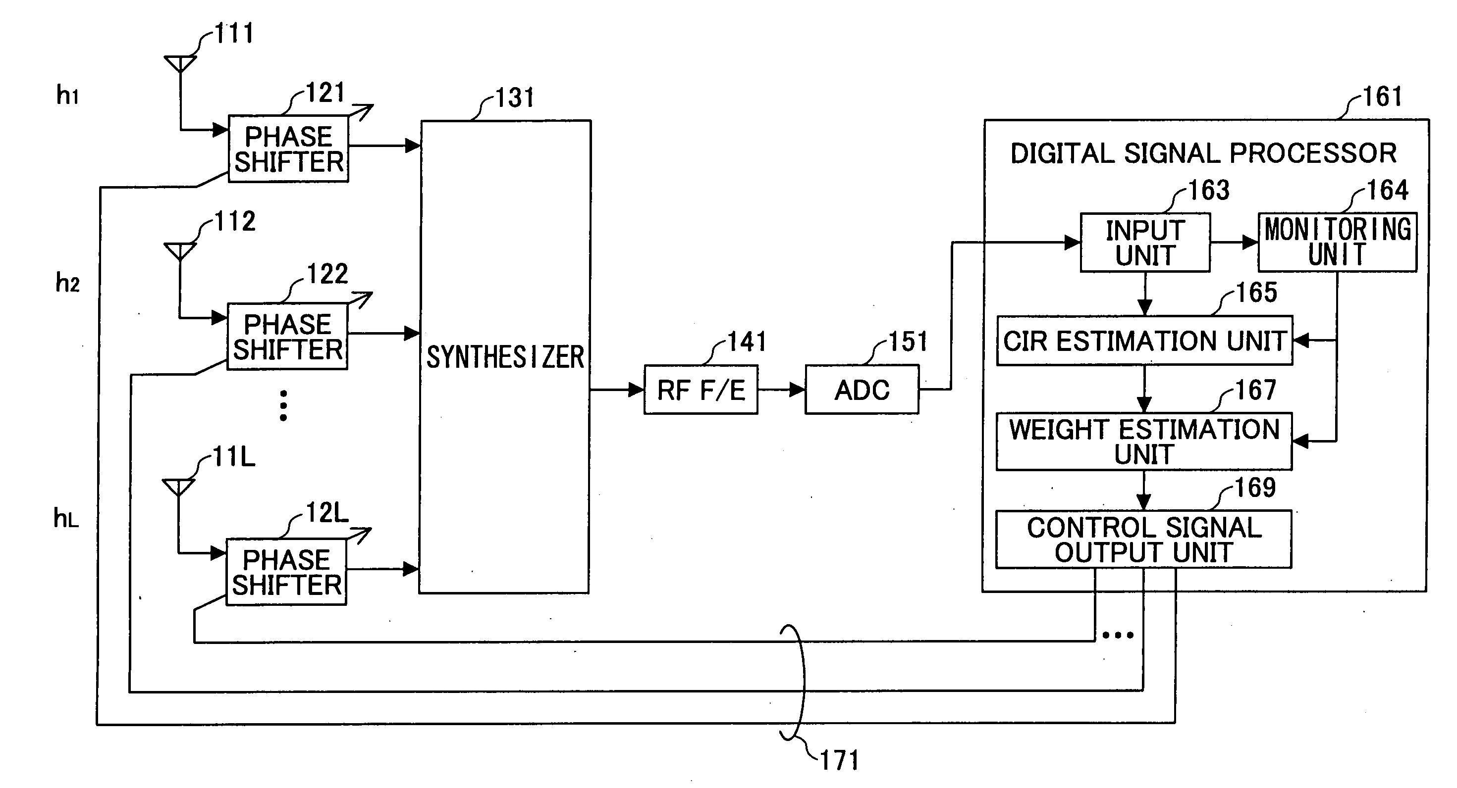
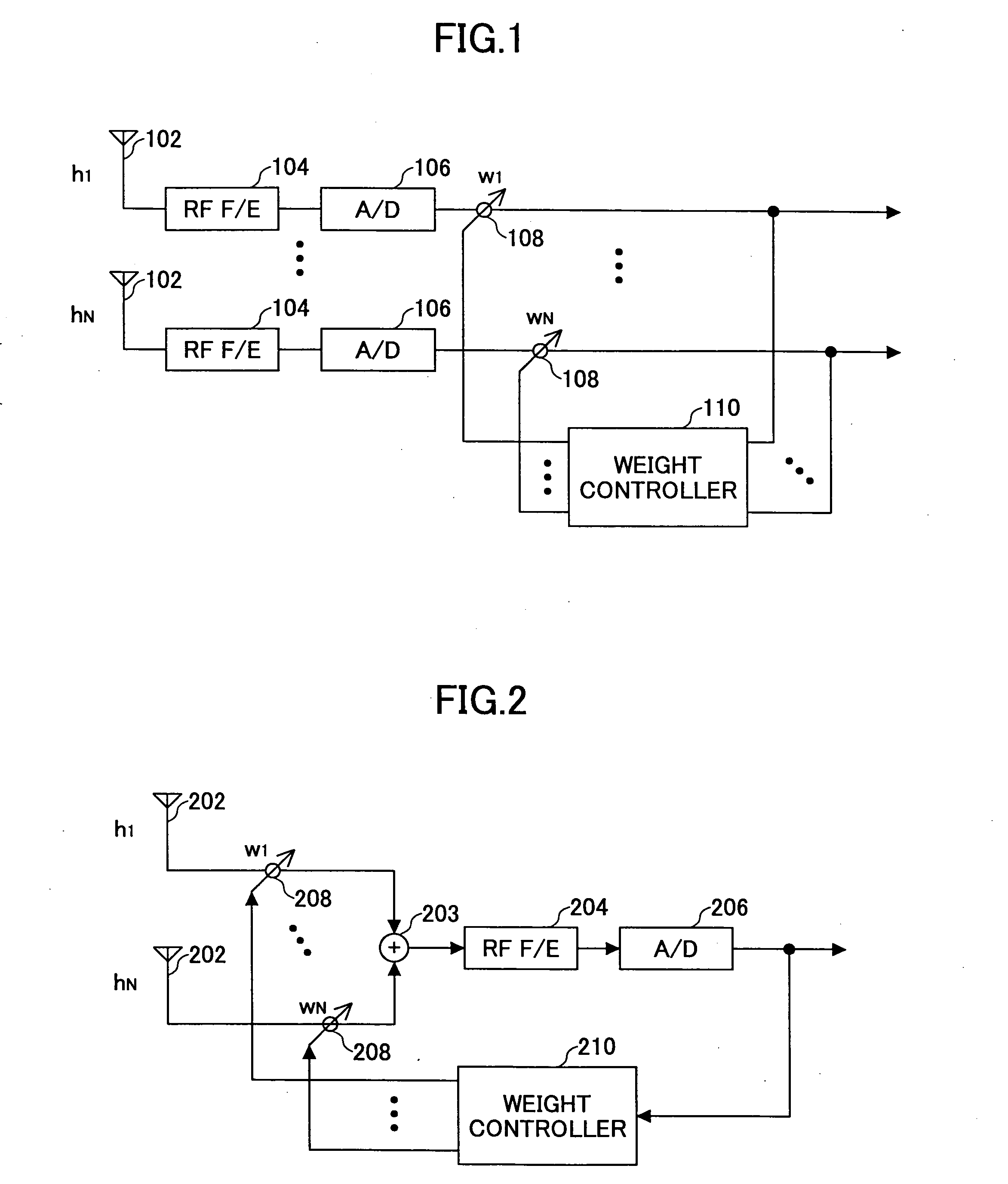
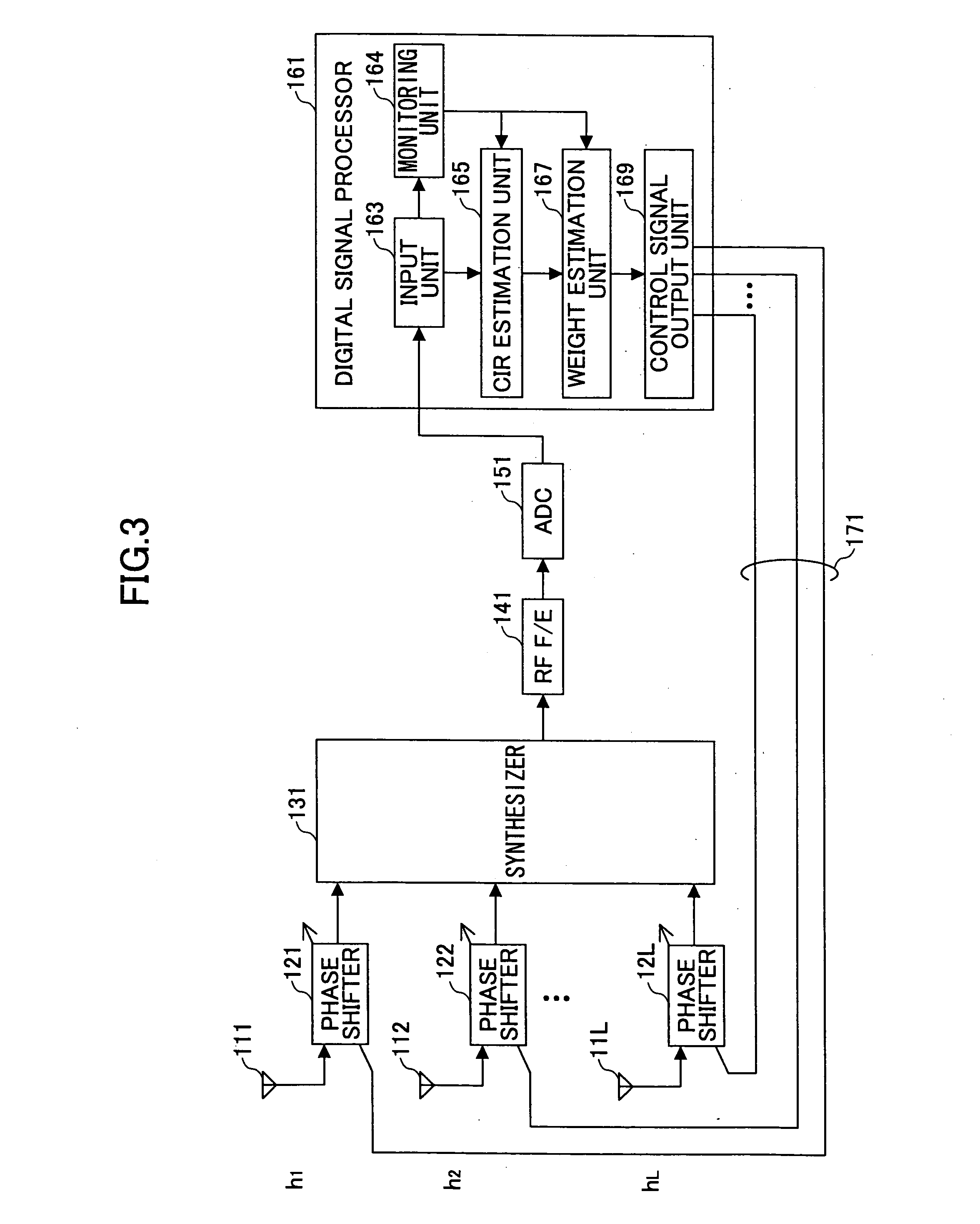
Array antenna system and weighting control technique used in array antenna system
a technology of array antennas and array antennas, applied in the field of wireless communication, can solve the problems of difficult definition, time and workload for optimization, and inability to allow the weighting coefficient to converge appropriately, and achieve the effect of optimum weighting coefficient promptly
- Summary
- Abstract
- Description
- Claims
- Application Information
AI Technical Summary
Benefits of technology
Problems solved by technology
Method used
Image
Examples
second embodiment
[0053]FIG. 7 is a block diagram of an adaptive array antenna system according to the invention. The adaptive array antenna system includes L antenna elements 211-21L, L variable gain-low noise amplifiers (VG-LNA) 221-22L, and L phase shifters 231-23L. The adaptive array antenna system also includes a synthesizer 241, an RF front end 251, an analog-to-digital converter 261, and a digital signal processor 271. The VG-LANs 221-221 and the phase shifters 231-23L are connected to the digital signal processor 271 via corresponding L control lines 281.
[0054] Each of the VG-LNAs 221-22L sets the amplitude of the signal received at the associated antenna element, based on the control signal supplied through the control line 281. Each of the phase shifters 231-23L sets the phase of the signal received at the associated antenna element, based on the control signal supplied through the control line 281. The synthesizer 241 synthesizes the L signals weighted by the respective phase shifters 231-...
fourth embodiment
[0060]FIG. 9 is a block diagram of an adaptive array antenna system according to the invention. In this embodiment, the adaptive array antenna system is applied to a multi-input-multi-output (MIMO) receiver. The receiver has multiple branches (the number of branches is, for example, Mr), each branch being provided with an adaptive array antenna having L antenna elements and L phase shifters, as in the previous embodiments. In the first branch, the signals received at L antenna elements 3111-311L are weighted by the associated phase shifters 3121-312L, synthesized by the synthesizer 3131, processed by the RF front end 3141, and digitized by the ADC 3151. The same applies to the other branches. Accordingly, the adaptive array antenna system includes synthesizers 3131-3Mr31, RF front ends 3141-3Mr41, and ADCs 3151-3Mr51. As many digital signals y1, y2, . . . , yα, . . . , yMr as the number of the branches are input to the digital signal processor 3161. The digital signal processor 3161...
fifth embodiment
[0063] FIG, 10 is a block diagram of an adaptive array antenna system according to the invention, which is applied to the time division duplex (TDD) scheme. The adaptive array antenna system includes L antenna elements 111-11L, L phase shifters 121-12L, and a switch 441 for switching between a received signal processing line and a transmitted signal processing line, both lines being connected to a digital signal processor 471. The received signal processing line includes a receiving front end 451 and an analog-to-digital converter (ADC) 461. The transmitted signal processing line includes a transmission front end 452 and a digital-to-analog converter (DAC) 462.
[0064] In the TDD scheme, the same frequency is used in transmitting and receiving signals. Accordingly, the optimum weighting coefficient set for receiving a signal can be used when transmitting a signal. Since weighting control is carried out in common between transmitting and receiving signals, the adaptive array antenna sy...
PUM
 Abstract
Description
Claims
Application Information
 - R&D
- Intellectual Property
- Life Sciences
- Materials
- Tech Scout
- Unparalleled Data Quality
- Higher Quality Content
- 60% Fewer Hallucinations
Browse by: Latest US Patents, China's latest patents, Technical Efficacy Thesaurus, Application Domain, Technology Topic, Popular Technical Reports.
© 2025 PatSnap. All rights reserved.Legal|Privacy policy|Modern Slavery Act Transparency Statement|Sitemap|About US| Contact US: help@patsnap.com


