Quantum resonance analytical instrument

an analytical instrument and quantum resonance technology, applied in instruments, interferometric spectrometry, optical radiation measurement, etc., can solve the problem of prior art in which shaped pulses have been used to recognize, identify or detect specific molecules or substances

Active Publication Date: 2005-08-25
MCGREW STEPHEN P
View PDF11 Cites 50 Cited by
  • Summary
  • Abstract
  • Description
  • Claims
  • Application Information

AI Technical Summary

Problems solved by technology

Whereas prior art has used shaped pulses to study the quantum dynamics of specific molecules, there is no p...

Method used


Image

  • Quantum resonance analytical instrument
  • Quantum resonance analytical instrument
  • Quantum resonance analytical instrument

Examples


embodiment # 1

Embodiment #1

Apparatus and Method for Detecting Anthrax Spores or Other Pathogens

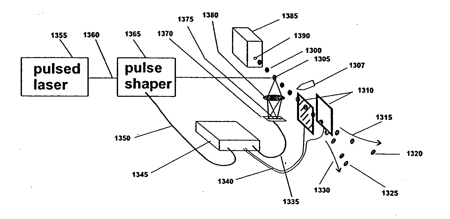
[0050] The apparatus of FIG. 12 includes a source 1200 of femtosecond light pulses, a pulse shaper 1210, a fluorescence spectrometer 1237, optics 1270 to direct shaped light pulses to a sample of fluid in a sample holder 1265, means 1237 for analyzing the spectrum and polarization of light emitted by the sample in response to illumination by a light pulse, and means 1217 for controlling the pulse shaper 1210. In the example shown in FIG. 12, the sample holder is a transparent capillary tube 1265, a source reservoir 1230, the tubing 1215 and 1250, and the receiver reservoir 1255. However, the sample holder can be a microscope slide, a “gene array chip”, a clamp, or any other device that can hold a sample for analysis. In fact, the sample holder can be the sample itself of part of the sample's environment, if, for example, the sample is a letter in a mail sorting facility, dust on a table surface, or mic...

embodiment # 2

Embodiment #2

A Pulse Shaper with Phase, Amplitude and Polarization Control

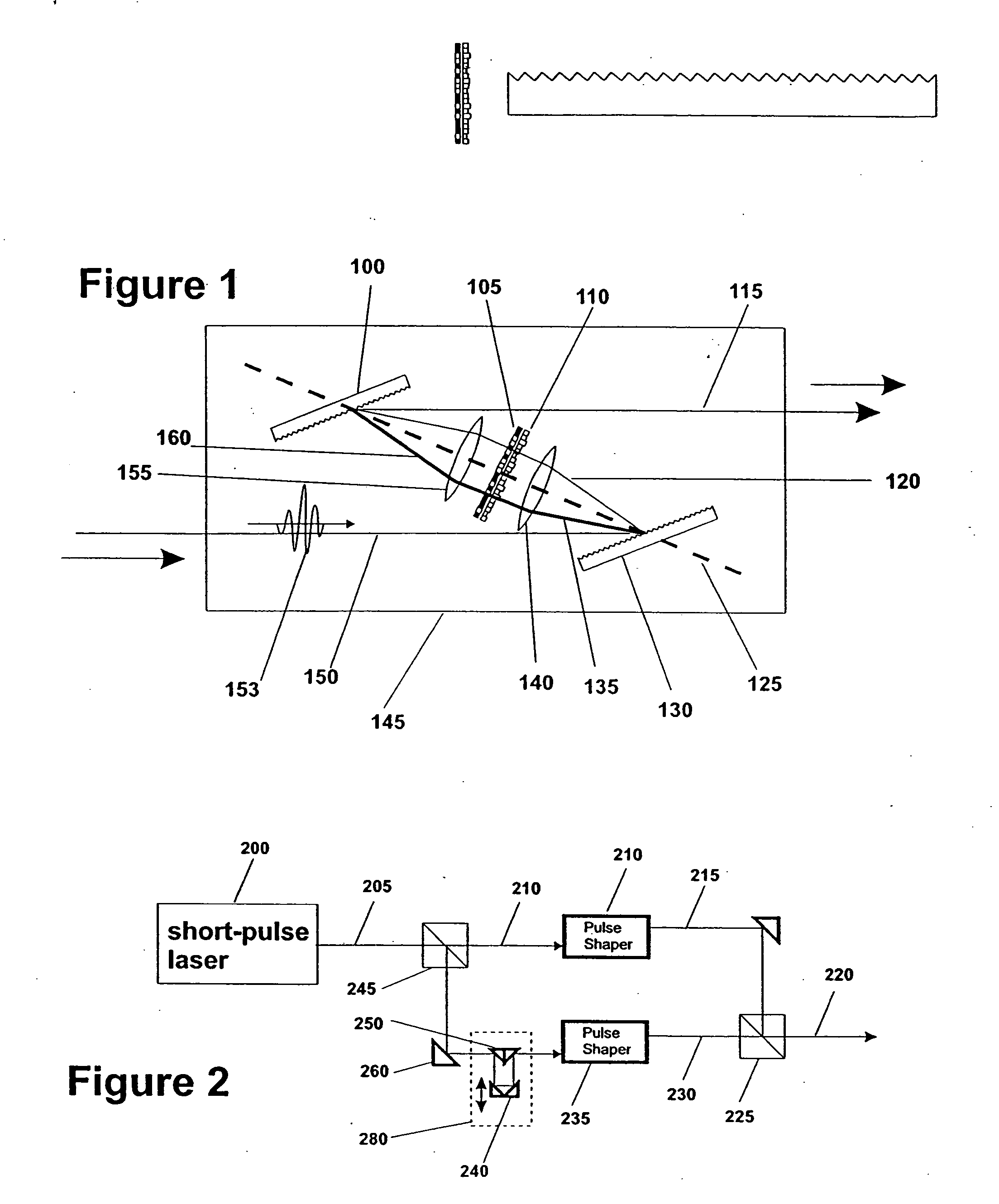
[0054] The apparatus in FIG. 7 is a pulse shaper for light pulses, on the order of femtoseconds to nanoseconds in duration. An original collimated pulse 701 is split by a polarizing beamsplitter 700 into two pulses 775, 702 with orthogonal polarization. In the path of each pulse, a non-polarization pulse shaper 710, 735, 740 is placed. As shown in FIG. 1, in the non-polarization pulse shapers, a dispersive element 130 such as a diffraction grating or a prism spreads the spectrum of an original light pulse out to a line. The diverging light in the spread spectrum is collimated by a lens 140 or by a curved mirror, then is passed through one or more spatial light modulators 110,105 to adjust the relative phase and amplitude of each spectral component relative to the other components. After passing through the spatial light modulators, the light is focused to a point by a second lens 155 onto a second diffraction...

embodiment # 3

Embodiment #3

Scanning Near-Field Optical Probe Microscope

[0055] As shown in FIG. 4, a shaped pulse of light may be coupled into an optical fiber 490 and thence into the optics 455, 460 of a near-field scanning optical probe microscope 450. Scattered light from the pulse and fluorescent light stimulated by the pulse may be gathered either by the optical fiber 447 or by other means such as a microscope objective and analyzed with respect to spectrum, polarization and phase by means of a spectrometer or time-resolved spectrometer and other suitable optics 435. Phase analysis requires interfering the gathered light with a portion of the original pulse and examining the position of fringes in the interference pattern. Scattered light may be analyzed for features in the absorption spectrum, while emitted fluorescent light may be analyzed for features in the emission spectrum. Any particular substance at the locus of the evanescent light field from the tip of the microscope probe will be ...


PUM


Abstract

Quantum resonance fluorescent microscope systems for detecting component substances in a specimen are described. The systems are based on exciting the sample containing the material with a femtosecond to nanosecond probe pulse of collimated light, which is tailored to optimize detection of a given material by separating the probe pulse into component features of frequency, polarization, phase and/or amplitude. The component features are independently shaped and formed into a composite pulse selected to optimize a signature response pulse received from the material. In some cases, two independently re-shaped pulses are combined, where one re-shaped pulse has two mixed polarization states and the other re-shaped pulse is linearly polarized. These two pulses are made to intersect at an angle of 90 degrees so that the combined pulse has electric field in each of the XYZ axes. Selection of the appropriate shapes for the component features of the pulses for a given material is accomplished by testing variations in the features on the material, assigning a fitness value to variants that tend to optimize a distinctive spectral response from the material, and using a genetic algorithm to select the combination of component features that enhances the distinctiveness of the response received over a typical background.

Description

CROSS-REFERENCE TO RELATED APPLICATIONS [0001] This application is a continuation-in-part of, and claims priority to, U.S. Pat. Ser. No. 10 / 286,338, filed Nov. 1, 2002, which claims priority to U.S. provisional patent application No. 60 / 338,506 entitled “Anthrax Detector” filed Nov. 6, 2001.TECHNICAL FIELD [0002] The invention relates to methods and devices for detecting materials in a sample by separating a coherent radiation pulse directed onto the sample into a plurality of pulses of different polarization sates, modulating the amplitude or phases of the separate pulses and coherently recombining the pulses into a composite pulse having component features selected by an evolutionary algorithm to distinguish the materials in the sample via the material's spectral response. BACKGROUND OF THE INVENTION [0003] Prior art includes a large body of published work relating to the shaping of femtosecond pulses and the interactions between various materials or molecules with the shaped puls...

Claims


Application Information

Patent Timeline
IPC IPC(8): G01N21/21G01N21/39
CPCB82Y10/00B82Y20/00G01N21/21G01N2021/396G01N21/6458G01N21/648G01N21/3581
Inventor MCGREW, STEPHEN P.
Owner MCGREW STEPHEN P
Why Eureka
Try Eureka