Seal construction for a fuel cell electrolyser and process for making a fuel cell with same

a technology of electrolyte and sealing structure, which is applied in the direction of cell components, final product manufacturing, sustainable manufacturing/processing, etc., can solve the problems of unsatisfactory resolution of the sealing effect, reduce the electric resistance of the sealing material, and achieve simple and cost-effective mounting, facilitating and particularly more process-secure

Inactive Publication Date: 2005-08-25
BAYERISCHE MOTOREN WERKE AG +1
View PDF2 Cites 10 Cited by
  • Summary
  • Abstract
  • Description
  • Claims
  • Application Information

AI Technical Summary

Benefits of technology

[0019] It is an object of the invention to provide a sealing structure for a fuel cell or an electrolyzer, particularly a solid-electrolyte fuel cell, which is insensitive to thermo-mechanical tensions and simultaneously ensures an electric (particularly an electronic) insulation; that is, an impermeability for electrons. Furthermore, the sealing structure according to the invention is to be producible in a simple and cost-effective manner, particularly in comparison to the state of the art, without additional working steps. In addition, the compressibility and / or the shrinkage characteristic of the sealing structure is to be adapted to that of the contacting layer and thus provide a facilitated and particularly more process-secure mounting.

Problems solved by technology

During the rapid heating of the fuel cell stack 1, this may result in thermally induced tension cracks in the sealing layer 14 and thus in a failure of its sealing effect.
Particularly for solid-electrolyte fuel cells, which are stressed by a frequent starting and switching-off of the operation, this represents a problem which has not been satisfactorily solved.
However, these additions frequently lead to a reduction of the electric resistance of the sealing material at the typically high operating temperatures of a solid-electrolyte fuel cell.
By way of the sealing layer 14 between a second separator plate 8 and a first separator plate 7 of two neighboring individual fuel cells 2, this results. in undesirable leak currents which impair the electric efficiency of a fuel cell stack 1.
Another disadvantage of the sealing device known according to FIG. 3 of the state of the art is that the materials for the sealing layer 14 have a compression behavior and / or shrinking behavior which differs in comparison to the contacting layer 6, whereby, during the mounting of the fuel cell stack 1, undesirable inaccuracies occur which may make a reliable contacting between the contacting layer 6 and an adjoining separator plate 7 doubtful.
Furthermore, it is disadvantageous that the providing of a suitable sealing layer 14 before the assembling of the fuel cell stack 1 requires high expenditures and cost because, for example, a sealing agent strand has to be established or, in the case of a foil-type construction of the sealing layer 14, the latter has to be produced separately and has to be positioned or inserted before the assembling process.
During the rapid heating of the fuel cell stack, this may result in thermally induced tension cracks in the sealings and thus in a failure of the sealing effect.
The difficulty now consists of coordinating the shrinkage behavior of the sealing layer and of the contacting layer.
The pasty ceramic suspensions normally used for the electric contacting shrink even at low temperatures and compact at temperatures higher than 400° C. In the case of glass-ceramic solders, the shrinking process starts only at temperatures >500° C. and is concluded only at temperatures >750° C. The two processes therefore do not take place simultaneously and frequently result in gas leakages, lack of electric contacting or a fracture of the SOFC (solid oxide fuel cell) because of locally excessive contact pressure forces.
However, the disadvantage of this sealing paste is an electric insulating capacity which is insufficient at the operating temperature.
When solid-electrolyte fuel cell stacks are used, this results in electric leak currents (short circuits) between the individual bipolar plates and thus results in power losses in the system.
However, this solution cannot be transferred to a solid-electrolyte fuel cell since, in the case of such a solid-electrolyte fuel cell (SOFC: solid-oxide fuel cell), no so-called wet electrodes or wet electrolytes exist, and thus the problem on which German Patent Document DE 19515457 C1 is based does not occur as a result of the type of construction.

Method used


Image

  • Seal construction for a fuel cell electrolyser and process for making a fuel cell with same
  • Seal construction for a fuel cell electrolyser and process for making a fuel cell with same
  • Seal construction for a fuel cell electrolyser and process for making a fuel cell with same

Examples


first embodiment

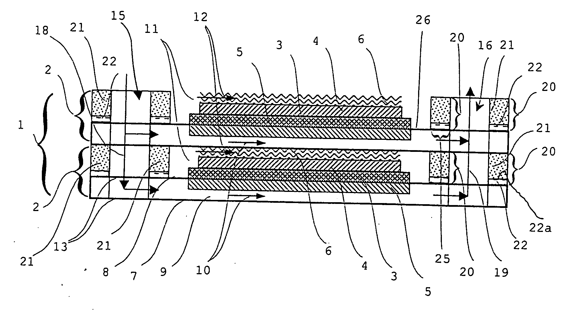
[0037] According to the sealing structure 20 according to the invention, the latter has a sealing layer 21 and an insulating layer 22. The insulating layer 22 consists of a metal oxide, particularly an aluminum oxide (Al2O3) which, in a particularly preferred manner, is constructed in the so-called z,900 -modification. Al2O3 in the z,900 -modification has a particularly high electric resistance and an excellent corrosion stability in oxidizing as well as in reducing media.

[0038] In an embodiment corresponding to FIG. 1, the insulating layer 22 is arranged in all required sealing areas 25 between two neighboring individual fuel cells 2 on a top side 26 of one of the bipolar plates 7, 8, which top side 26 faces an oxidation space 11. The arrangement of the sealing layer 21 on a free surface of a bipolar plate 7, 8 is advantageous particularly when the bipolar plates 7, 8 are produced from a steel material with a high aluminum content (>2%). In this case, the aluminum oxide insulating ...

second embodiment

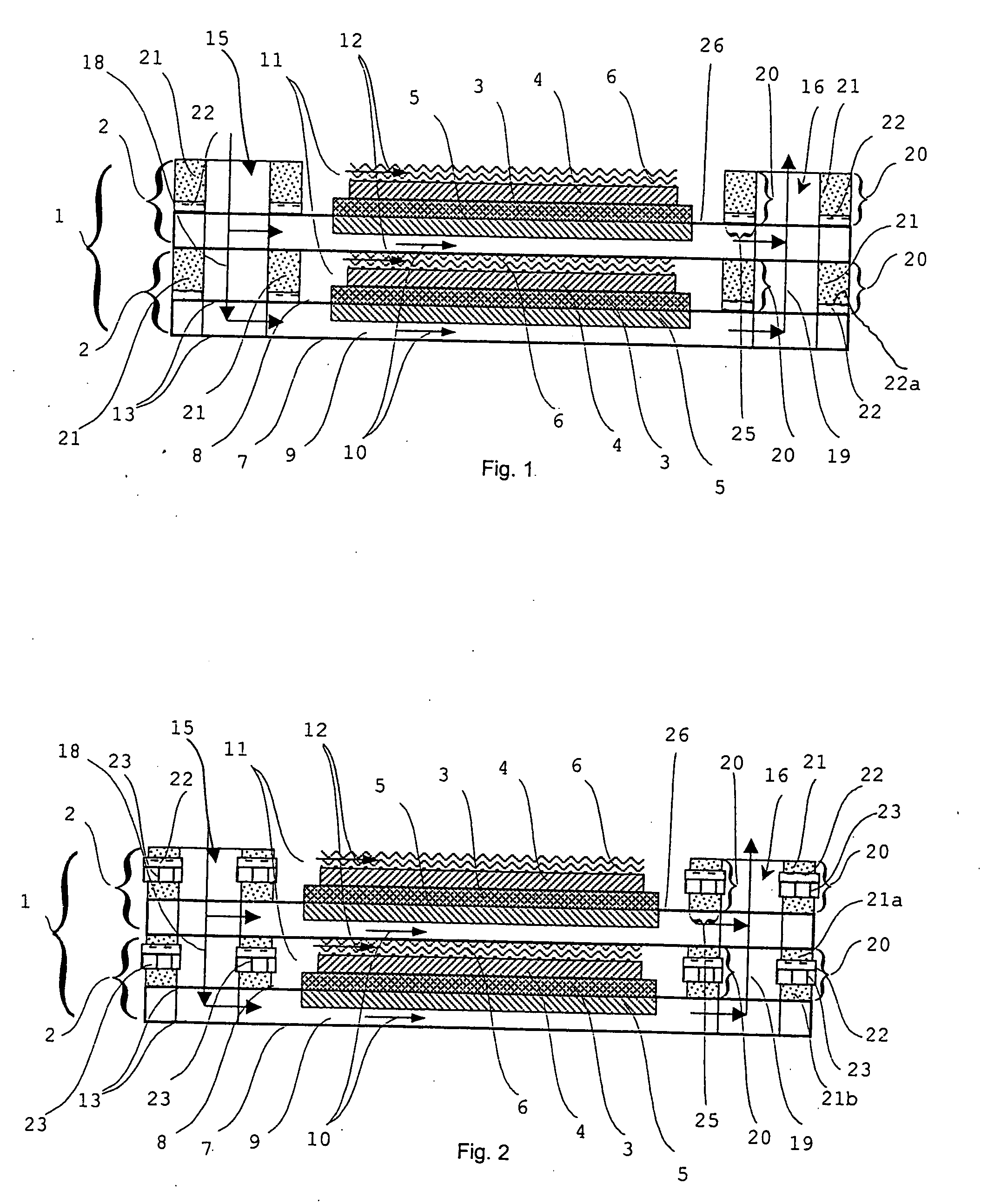
[0043] In the sealing structure of the invention corresponding to FIG. 2, the insulating layer 22 is arranged on a carrier layer 23, in which case a first sealing layer 21a is arranged between the insulating layer 22 and a neighboring separator plate 7, and a sealing layer 21b is arranged between the carrier layer 23 and its neighboring separator plate 8. Thus, in this embodiment, the sealing structure 20 has at least four layers, having at least one carrier layer 23, at least one insulating layer 22 and at least two sealing layers 21a, 21b.

[0044] In this embodiment, the insulating layer 22 is constructed of the same material as the insulating layer 22 of an embodiment corresponding to FIG. 1. The sealing layers 21a, 21b are preferably constructed of the same material as the sealing layer 21 of an embodiment corresponding to FIG. 1. The carrier layer 23 is, for example, a steel plate with a high aluminum content (>2%). In the case of such steel plates, at temperatures above 900° C....


PUM

PropertyMeasurementUnit
temperatureaaaaaaaaaa
temperaturesaaaaaaaaaa

Abstract

A sealing structure in a fuel cell and/or an electrolyzer (particularly a solid-oxide fuel cell and/or a solid-oxide electrolyzer) is arranged between neighboring separator plates of a cell stack. The sealing structure is constructed in at least two layers, including at least one insulating layer and at least one sealing layer.

Description

[0001] This application claims the priority of German Patent document DE 103 021 24.8, filed 21 Jan. 2003. FIELD OF THE INVENTION [0002] This invention relates to a sealing structure for a fuel cell or an electrolyzer, to a method of producing the sealing structure, and to a fuel cell or an electrolyzer. BACKGROUND OF THE INVENTION [0003] A conventional fuel cell stack 1, shown in FIG. 3, has two or more individual fuel cells 2 which are stacked above one another in the manner of a tower. Each fuel cell 2 has an electrolyte layer 3, a cathode layer 4 arranged on one flat side of the electrolyte layer 3, and an anode layer 5 arranged on the other flat side of the electrolyte layer 3. For contacting a neighboring fuel cell 2, a contacting layer 6 is disposed on the cathode layer 4. [0004] In addition, each individual fuel cell 2 has first and second separator plates 7, 8 that bound a combustible-gas space 9, into which the anode layer 5 projects. The combustible-gas space 9 is connect...

Claims


Application Information

Patent Timeline
Patent Type & Authority Applications(United States)
IPC IPC(8): H01M2/08H01M8/12H01M8/24
CPCH01M8/0282Y02E60/50H01M8/2425H01M8/0286H01M8/2432H01M8/2483Y02P70/50H01M8/0271
Inventor FINKENWIRTH, OLAVKUHN, BERNDZERFASS, HANS-RAINER
Owner BAYERISCHE MOTOREN WERKE AG
Why Eureka
Try Eureka