System and method for variable speed operation of a screw compressor

a screw compressor and variable speed technology, which is applied in the direction of positive displacement liquid engines, liquid fuel engines, lighting and heating apparatus, etc., can solve the problems of reduced efficiency increased cost and maintenance of the compressor system, and limited speed of the rotors of the screw compressor, so as to improve the efficiency of screw compressor operation, reduce gas leakage, and increase the speed of the rotor speed

Active Publication Date: 2005-09-01
JOHNSON CONTROLS TYCO IP HLDG LLP
View PDF36 Cites 66 Cited by
  • Summary
  • Abstract
  • Description
  • Claims
  • Application Information

AI Technical Summary

Benefits of technology

[0008] One advantage of the present invention is more efficient screw compressor operation from increased rotor speeds that reduce gas leakage and increase the rotor seal.
[0009] Another advantage of the present invention is that the operating efficiency, speed and horsepower of an induction motor can be increased.
[0010] Still another advantage of the present invention is that increased system efficiency can be obtained at part or partial load conditions.
[0011] A further advantage of the present

Problems solved by technology

In the past, the speed of the rotors of a screw compressor was limited to the maximum rated output speed of the induction motor driving the rotors of the screw compressor.
However, the introduction of the gearing arrangement to obtain increased rotor speeds in the screw compressor resulted in a reduction in the efficiency of the compressor system and increased cost and maintenance for the compressor system.
In addition, the screw compressor still only has one output capacity because the rotors are still being driven at a single (albeit faster) speed.
While the incorporation of a slide valve can provide a variable output

Method used


Image

  • System and method for variable speed operation of a screw compressor
  • System and method for variable speed operation of a screw compressor
  • System and method for variable speed operation of a screw compressor

Examples


Embodiment Construction

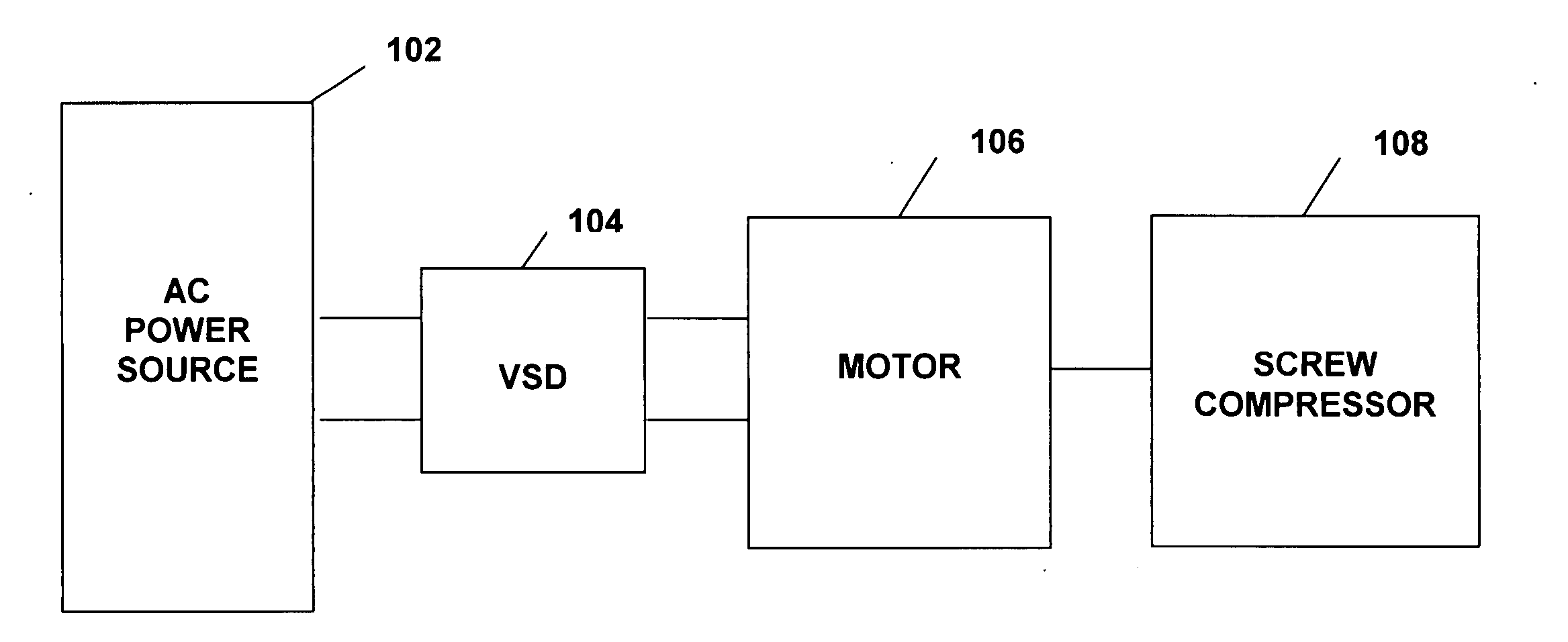
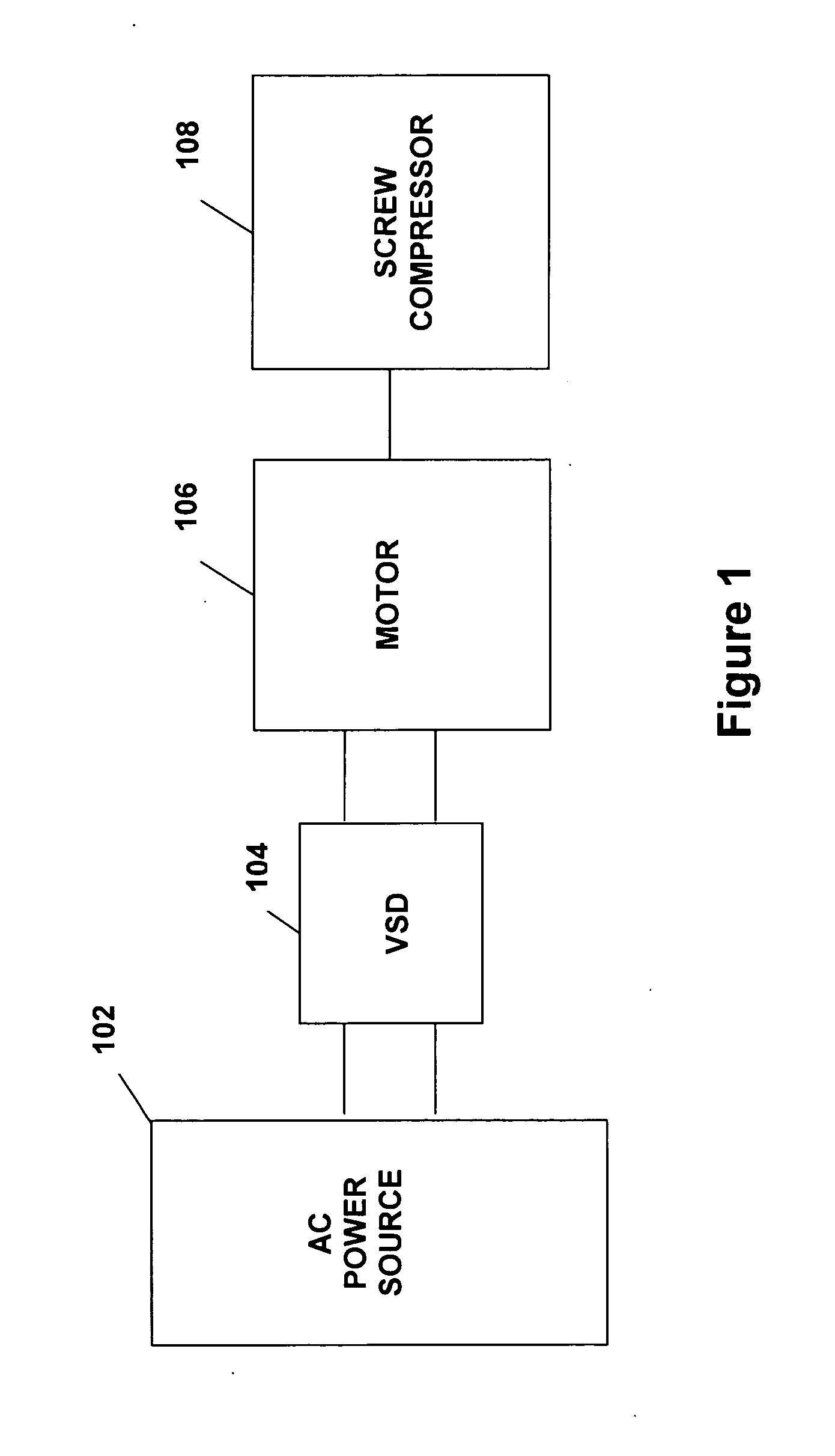
[0019]FIG. 1 illustrates generally the system configuration of the present invention. An AC power source 102 supplies a variable speed drive (VSD) 104, which powers a motor 106 that drives a screw compressor 108. The AC power source 102 provides single phase or multi-phase (e.g., three phase), fixed voltage, and fixed frequency AC power to the VSD 104 from an AC power grid or distribution system that is present at a site. The AC power source 102 preferably can supply an AC voltage or line voltage of 200 V, 230 V, 380 V, 460 V, or 600 V, at a line frequency of 50 Hz or 60 Hz, to the VSD 104 depending on the corresponding AC power grid.

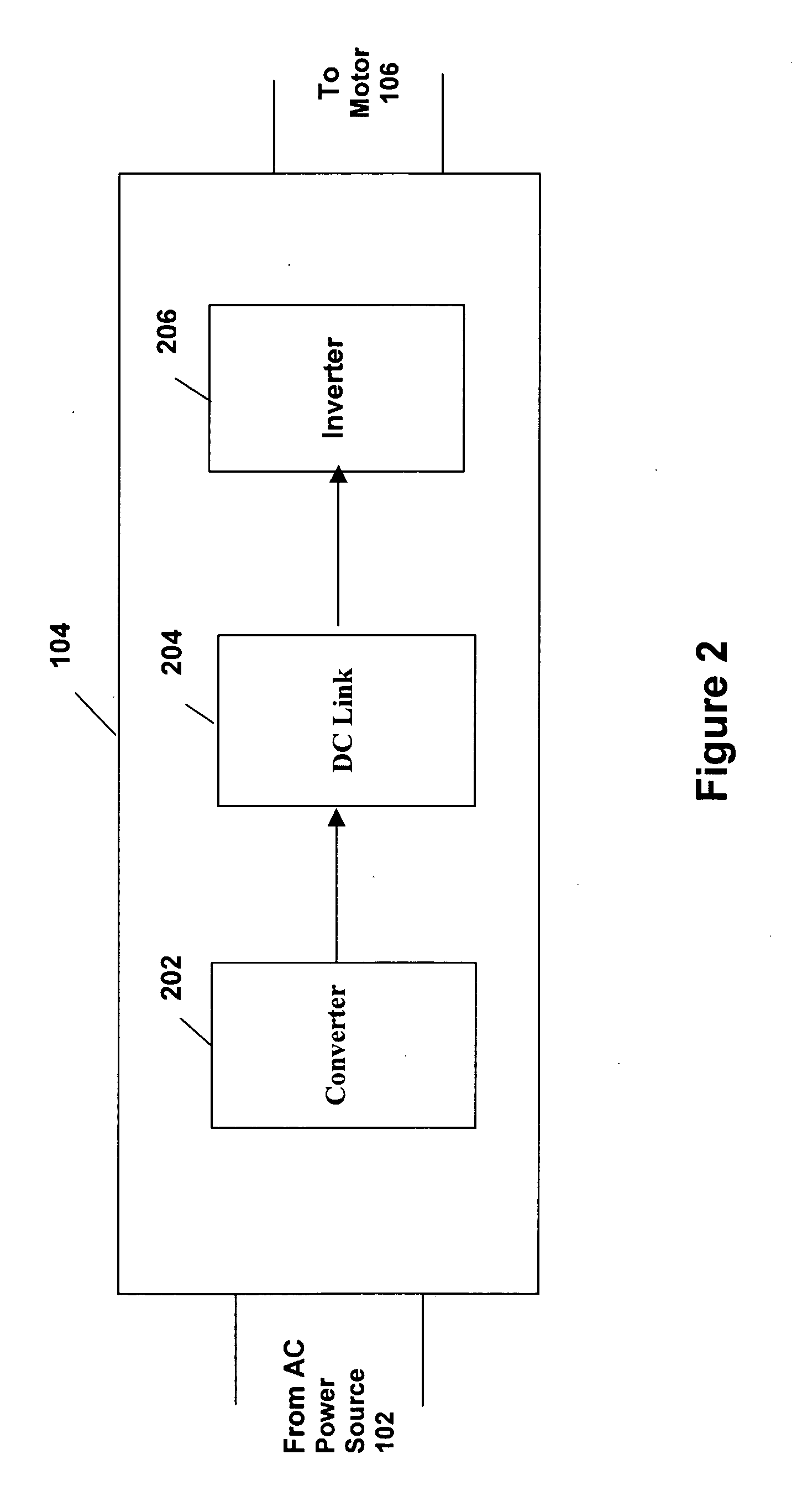
[0020] The VSD 104 receives AC power having a particular fixed line voltage and fixed line frequency from the AC power source 102 and provides AC power to the motor 106 at a desired voltage and desired frequency, both of which can be varied to satisfy particular requirements. Preferably, the VSD 104 can provide AC power to the motor 106 having higher v...


PUM


Abstract

A system and method are provided for variable speed operation of a screw compressor to obtain increased capacity and efficiency. The screw compressor is connected to an induction motor driven by a variable speed drive, wherein the screw compressor has a variable output capacity that is dependent on the output speed of the motor. To obtain increased capacity and efficiency, the screw compressor is operated at a speed greater than the screw compressor's rated speed and does not include a slide valve. The maximum operating speed of the screw compressor, which speed is greater than the rated speed, is related to the maximum operating speed of the motor when operated at a voltage and frequency provided by the variable speed drive that is greater than the motor's rated voltage and frequency in a constant flux or constant volts/Hz mode.

Description

BACKGROUND OF THE INVENTION [0001] The present invention relates generally to the operation of a screw compressor. More specifically, the present invention relates to the variable speed operation of a screw compressor connected to a motor powered by a variable speed drive that can provide the motor an input voltage and frequency greater than the motor's rated voltage and frequency. [0002] The capacity of a screw compressor is based on the amount of gas entering the screw compressor and the rotational speed of the screws or rotors compressing the gas. In the past, the speed of the rotors of a screw compressor was limited to the maximum rated output speed of the induction motor driving the rotors of the screw compressor. This single speed screw compressor would have a single output capacity based upon the rotor speed in the screw compressor. To get a rotor speed greater than the maximum rated speed of the induction motor and a corresponding increase in the output capacity of the screw...

Claims


Application Information

Patent Timeline
IPC IPC(8): F04C18/16F04C28/08F04C29/00H02M5/458H02P27/04
CPCF04C18/16F04C29/0085F04C28/08F25B1/047F25B49/025F25B2400/075F25B2400/13F25B2600/0253Y02B30/70H02P27/04
Inventor WILLS, FRANK EUGENESCHNETZKA, HAROLD ROBERTKESTER, DOUGLAS ALANJUDGE, JOHN F.VALIYA NADUVATH, MAHESHFEDERMAN, ISRAEL
Owner JOHNSON CONTROLS TYCO IP HLDG LLP
Why Eureka
Try Eureka