Gas processing apparatus and method and computer storage medium storing program for controlling same

a technology of computer storage medium and processing apparatus, which is applied in the direction of process and machine control, fluid pressure control, instruments, etc., can solve the problems of further cost increase of the apparatus itself, inability to properly cope with the case, and increase of the operation cost of the apparatus

Inactive Publication Date: 2005-09-01
TOKYO ELECTRON LTD
View PDF8 Cites 46 Cited by
  • Summary
  • Abstract
  • Description
  • Claims
  • Application Information

AI Technical Summary

Benefits of technology

[0018] It is, therefore, a primary object of the present invention to provide a processing apparatus and method and a computer readable storage medium storing therein a program for controlling same, wherein a pressure ...

Problems solved by technology

H10-11152 (Pages 2 to 4 and FIGS. 1 to 5)], the ballast gas whose flow rate is controlled is to be introduced to the pumping system, so that it cannot properly cope with a case where there is a big change in the processing pressure.
Further, a large amount of unnecessary nonreactive gas is employed, resulting in an operation cost increase for the apparat...

Method used


Image

  • Gas processing apparatus and method and computer storage medium storing program for controlling same
  • Gas processing apparatus and method and computer storage medium storing program for controlling same
  • Gas processing apparatus and method and computer storage medium storing program for controlling same

Examples


first embodiment

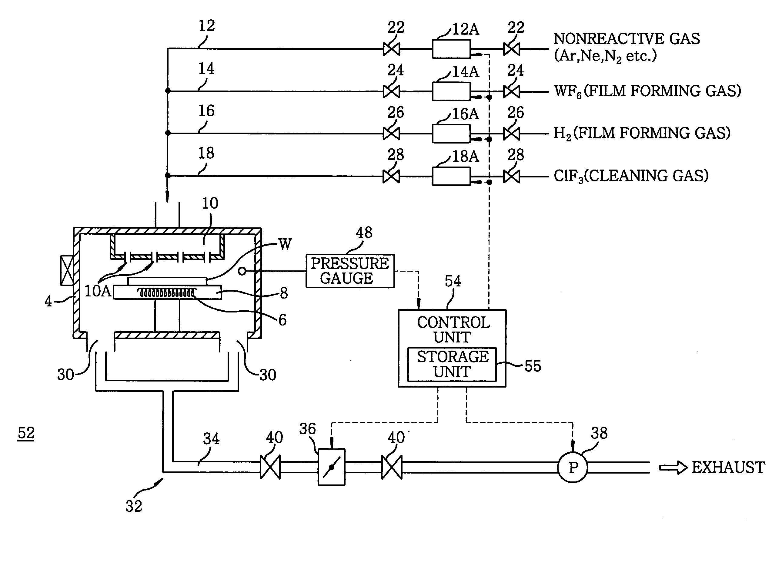
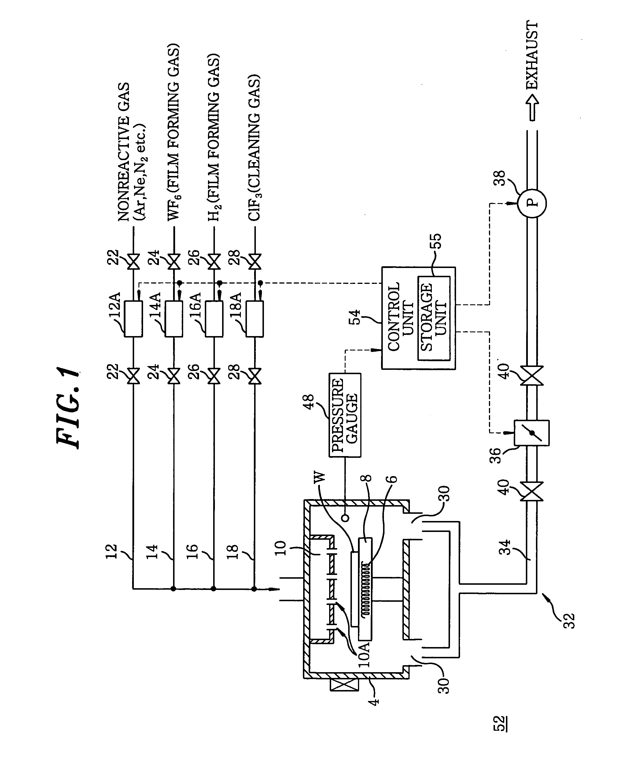
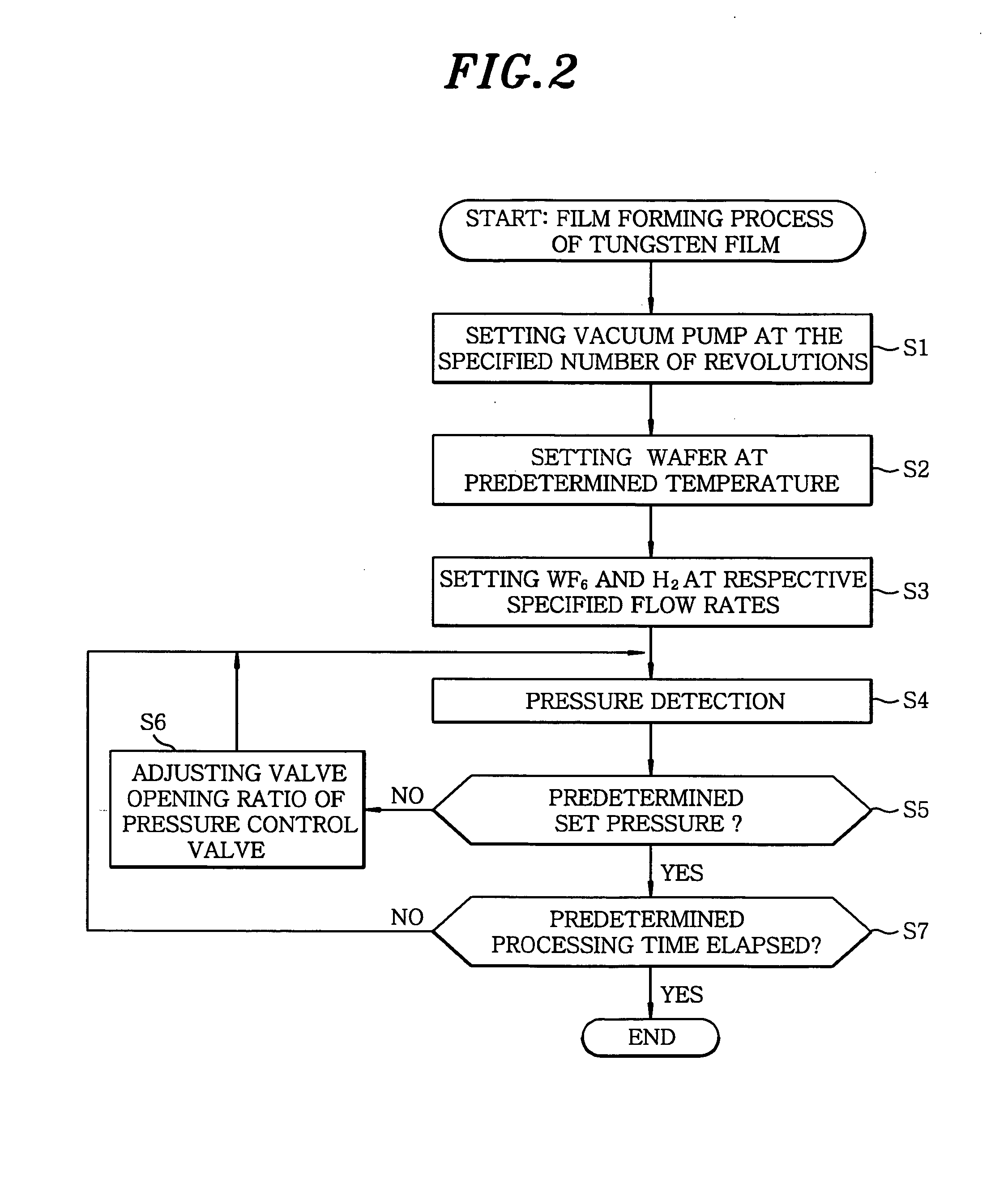
[0038]FIG. 1 is a schematic diagram showing a first embodiment of a processing apparatus in accordance with the present invention; FIG. 2 is a flowchart showing an embodiment of process in accordance with a first processing method; FIG. 3 is a flowchart showing an embodiment of process in accordance with a second processing method; FIG. 4 is a cross sectional view showing an embodiment of mounting table in case when a pre-cleaning process is carried out; and FIG. 5 is a flowchart showing an embodiment of process in accordance with a third processing method. Identical reference numerals will be assigned and explained for corresponding parts having substantially the same functions and configurations with those in FIG. 8. Further, the term “a process wherein a partial pressure of a processing gas is relatively important” to be explained below means a low processing pressure process (low pressure process), and the term “a process wherein a partial pressure of a processing gas is relativ...

second embodiment

[0068] In the aforementioned embodiment, such a case has been explained by using an example where an integrated exhaust line 34 is installed and one vacuum pump 38 is installed therein, as shown in FIG. 1. However, in case when pumping capacity is insufficient with one vacuum pump 38, a configuration of a second embodiment shown in FIG. 6 may be adopted. Namely, in this case, a second vacuum pump 60 formed of, e.g., a turbo molecular pump, is installed in series with the pressure control valve 36, and a bypass exhaust path 62 is connected to the exhaust line 34 such that it bypasses the pressure control valve 36 and the second vacuum pump 60. Further, a converting opening / closing valve 64 is installed in the bypass exhaust path 62. An inner diameter of the bypass exhaust path 62 is about in the range from 25 to 40 mm.

[0069] In this embodiment, the opening / closing valves 40 of the exhaust line 34 are first closed in case when vacuum-exhausting the inside of the processing vessel 4; ...

third embodiment

[0070] Next, a third embodiment of the present invention will be explained.

[0071]FIG. 7 is a schematic diagram showing a third embodiment of a processing apparatus in accordance with the present invention. Identical reference numerals will be assigned and explained for corresponding parts having substantially the same functions and configurations with those in FIGS. 1, 6 and 8. Further, the term “a relatively low processing pressure process” explained herein means a process wherein a partial pressure of a processing gas is important as was explained before, and the term “a relatively high processing pressure process” means a process wherein a partial pressure of a processing gas is unimportant.

[0072] As shown in FIG. 7, in the main exhaust line 34, there are installed the pressure control valve 36, the second vacuum pump 60 formed of, e.g., a turbo molecular pump and the first vacuum pump 38 formed of, e.g., a dry pump, in this order from the upstream side to the downstream side t...


PUM

PropertyMeasurementUnit
Partial pressureaaaaaaaaaa
Pressureaaaaaaaaaa
Flow rateaaaaaaaaaa

Abstract

A processing apparatus includes a processing vessel, a gas introduction unit, a processing gas supply unit, a nonreactive gas supply unit, a vacuum pumping unit, a pressure gauge and a control unit. The control unit controls a valve opening ratio of a pressure control valve based on a detection value of the pressure gauge while making a processing gas flow to a flow rate controller of the processing gas supply unit at a constant flow rate when performing a process in which a partial pressure of the processing gas is important. Meanwhile, when performing a process wherein the partial pressure of the processing gas is relatively unimportant, the control unit fixes the valve opening ratio of the pressure control valve at a predetermined value, and operating a flow rate controller of the nonreactive gas supply unit to control a flow rate based on the detection value.

Description

[0001] This application is a Continuation-In-Part of PCT International Application No. PCT / JP03 / 014266 filed on Nov. 10, 2003, which designated the United States. FIELD OF THE INVENTION [0002] The present invention relates to a processing apparatus and method for performing specific processes on, e.g., a semiconductor wafer and the like, and a computer readable storage medium storing therein a program for controlling same. BACKGROUND OF THE INVENTION [0003] Generally, for fabricating a semiconductor integrated circuit, various processes, such as a film forming process, an etching process, a thermal oxidation process, a diffusion process, a reforming process, a crystallization process and the like, are performed repeatedly on an object to be processed such as a semiconductor wafer to form a desired integrated circuit. Further, in order to remove unnecessary films or particles deposited to a processing vessel and the like, a cleaning process for removing the above-mentioned unnecessar...

Claims


Application Information

Patent Timeline
IPC IPC(8): C23F1/00G05D16/20H01L21/00H01L21/683
CPCH01L21/67109G05D16/2026H01L21/6831H01L21/67253
Inventor KASAI, SHIGERUISHIBASHI, SEIJIYAMAMOTO, KAORUTANAKA, SUMIYANAGITANI, KENICHI
Owner TOKYO ELECTRON LTD
Why Eureka
Try Eureka