Heat exchange device

Inactive Publication Date: 2005-09-01
UNIVERSITY OF ROCHESTER
View PDF21 Cites 9 Cited by
  • Summary
  • Abstract
  • Description
  • Claims
  • Application Information

AI Technical Summary

Benefits of technology

[0023] Accordingly, it is a principal object of the present invention to provide a heat exchange device having fins with sides approximately in the shape of an arc of a circle to maximize the heat tra

Problems solved by technology

On a macroscopic scale, when an energy source is used to move two materials that are in contact with each other, such as a rotating shaft on a bushing, the irregularities on the surface of the two materials interact, causing friction and the conversion of some of the source energy to thermal energy.
In those examples, the change in the internal energy of the system, that is, the conversion of energy to thermal energy, reflects the fact that systems are not one-hundred percent efficient.
The challenge in designing a heat exchange device that takes advantage of those heat transfer mechanisms is to design one that balances efficiency with economics.
Often, the most efficient heat exchange devices are expensive to manufacture and operate.
Less expensive devices may not achieve the desired heat transfer efficiency.
Therefore, operating costs assoc

Method used


Image

  • Heat exchange device
  • Heat exchange device
  • Heat exchange device

Examples


Example

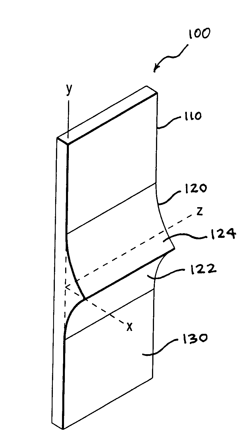
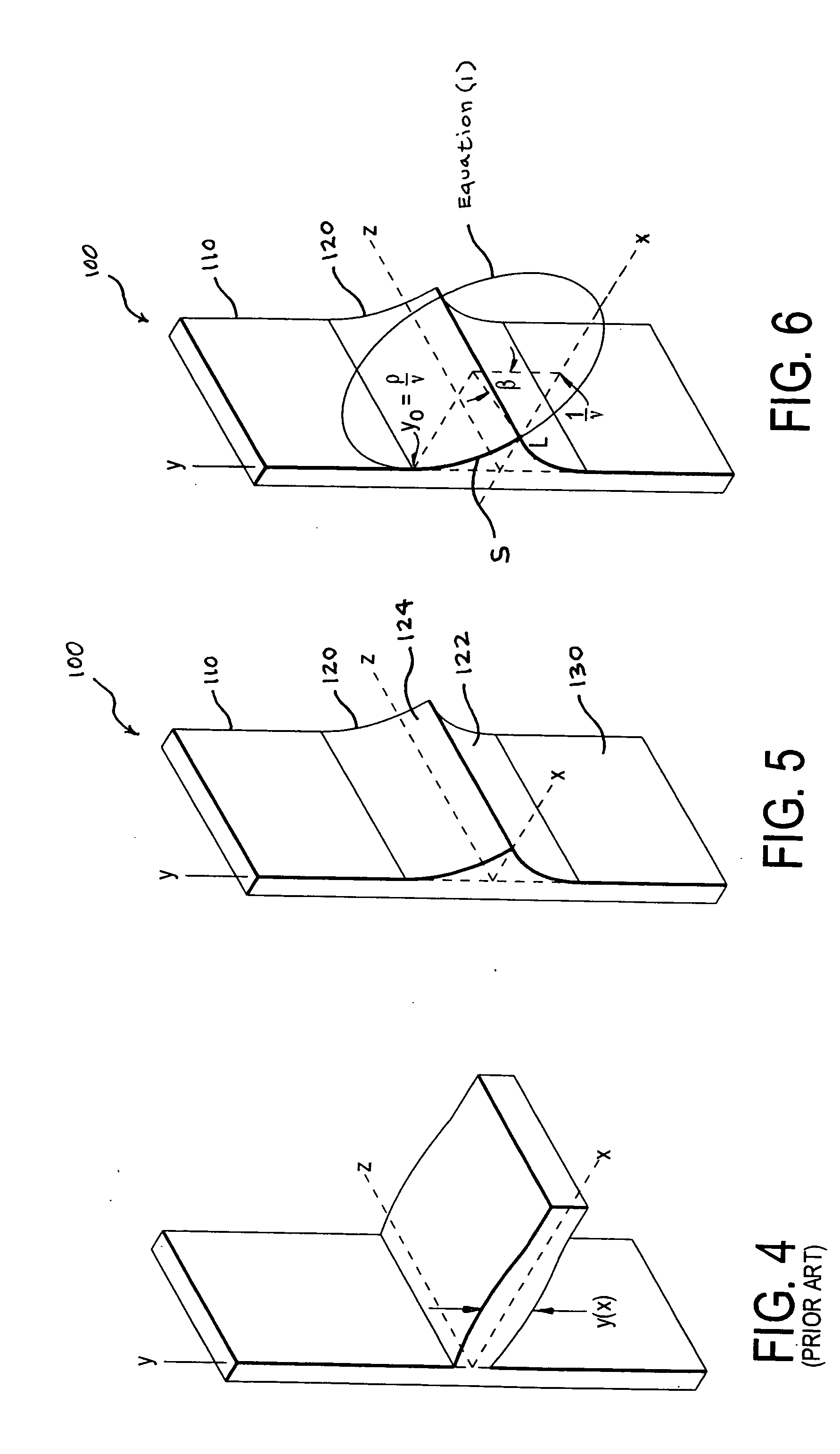
[0035] In the present invention, one preferred embodiment is described for illustrative purposes, it being understood that other embodiments are also within the scope of the invention. Turning first to FIG. 5, there is shown a perspective view drawing of a heat exchange device 100 having a heat source 110 and an approximately circular-arc-shaped fin 120 attached thereto.

[0036] The heat source 110 represents a component of a system that, by conduction, convection or radiation mechanisms, receives waste thermal energy generated by the system. For example, the heat source 110 may be a printed circuit board that has embedded heat-generating transistor circuits. The heat source 110 may also be a metal plate that is heated by exposure to a radiation source. It could also be part of the wall of a heat exchange tube that encloses a high temperature fluid passing through the tube. In FIG. 5, the heat source 110 is shown with orthogonal dimensions defined by an x-y-z coordinate system for ea...


PUM

PropertyMeasurementUnit
Temperatureaaaaaaaaaa
Widthaaaaaaaaaa
Energyaaaaaaaaaa

Abstract

A heat transfer device having a heat source for collecting waste heat from a heat-generating system, the heat transfer device having fins in which the shape of the sides of the fins is preferably circular according to the general expression (x-1γ)2+(y-ργ)2=1γ2,
where γ=hk,
h is the heat transfer coefficient between the fin and the surrounding fluid, k is the thermal conductivity of the fin material, ρ=qokθo,qo
is the heat flow through the fin semi-base per unit depth and θ0 is the difference between the temperatures of the heated surface and the surrounding fluid.

Description

BACKGROUND OF THE INVENTION [0001] 1. Field of the Invention [0002] The present invention relates to heat exchange devices and, more particularly, to a heat dissipating fin associated with a heat exchange device. [0003] 2. Description of the Related Art [0004] Whenever energy is used to perform work, part of the energy may be converted to thermal energy in accordance with the first law of thermodynamics. For example, when energy in the form of a voltage potential is used to cause electrons to move in conductive materials, such as, for example, in a transistor, part of the energy is converted to thermal energy. On a macroscopic scale, when an energy source is used to move two materials that are in contact with each other, such as a rotating shaft on a bushing, the irregularities on the surface of the two materials interact, causing friction and the conversion of some of the source energy to thermal energy. [0005] In those examples, the change in the internal energy of the system, tha...

Claims


Application Information

Patent Timeline
IPC IPC(8): F28F1/10F28F3/04F28F13/00
CPCF28F1/10F28F3/04Y10T29/49378Y10T29/49377F28F13/00
Inventor HANIN, LEONIDCAMPO, ANTONIO
Owner UNIVERSITY OF ROCHESTER
Why Eureka
Try Eureka