
Ion mobility spectrometer

a spectrometer and mobility technology, applied in the field of instrumentation and methodology for characterization of chemical samples, can solve the problems of inability to achieve the effect of improving analytical performance, and reducing the cost of characterization

Inactive Publication Date: 2005-09-01
IONWERKS
View PDF22 Cites 42 Cited by
  • Summary
  • Abstract
  • Description
  • Claims
  • Application Information

AI Technical Summary

Benefits of technology

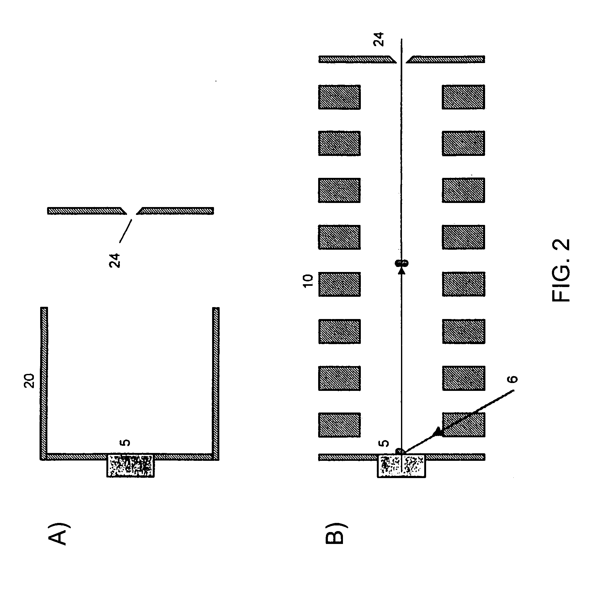
[0024] The above-described embodiments possess further specific embodiments related to the ionizing beam and it associated devices. Preferably, the ionizing beam is a laser, but it may be any known, useful ionization source. In one embodiment, one or more mirrors are used to redirect the ionizing beam to the sample to be ionized. This allows flexibility in the positioning of the ionization source. A number of embodiments use different sample holders which contain the sample for ionization. A rotatable sample holder for sequential sample ionization is another embodiment. Alternatively, a moving belt sample holder may be used. Preferably, the sample holder is positioned orthogonally to the drift cell axis.
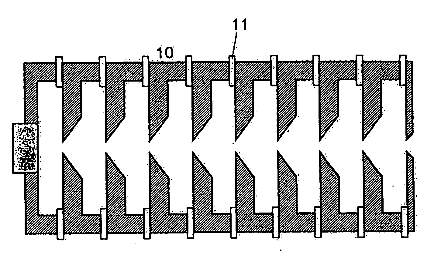
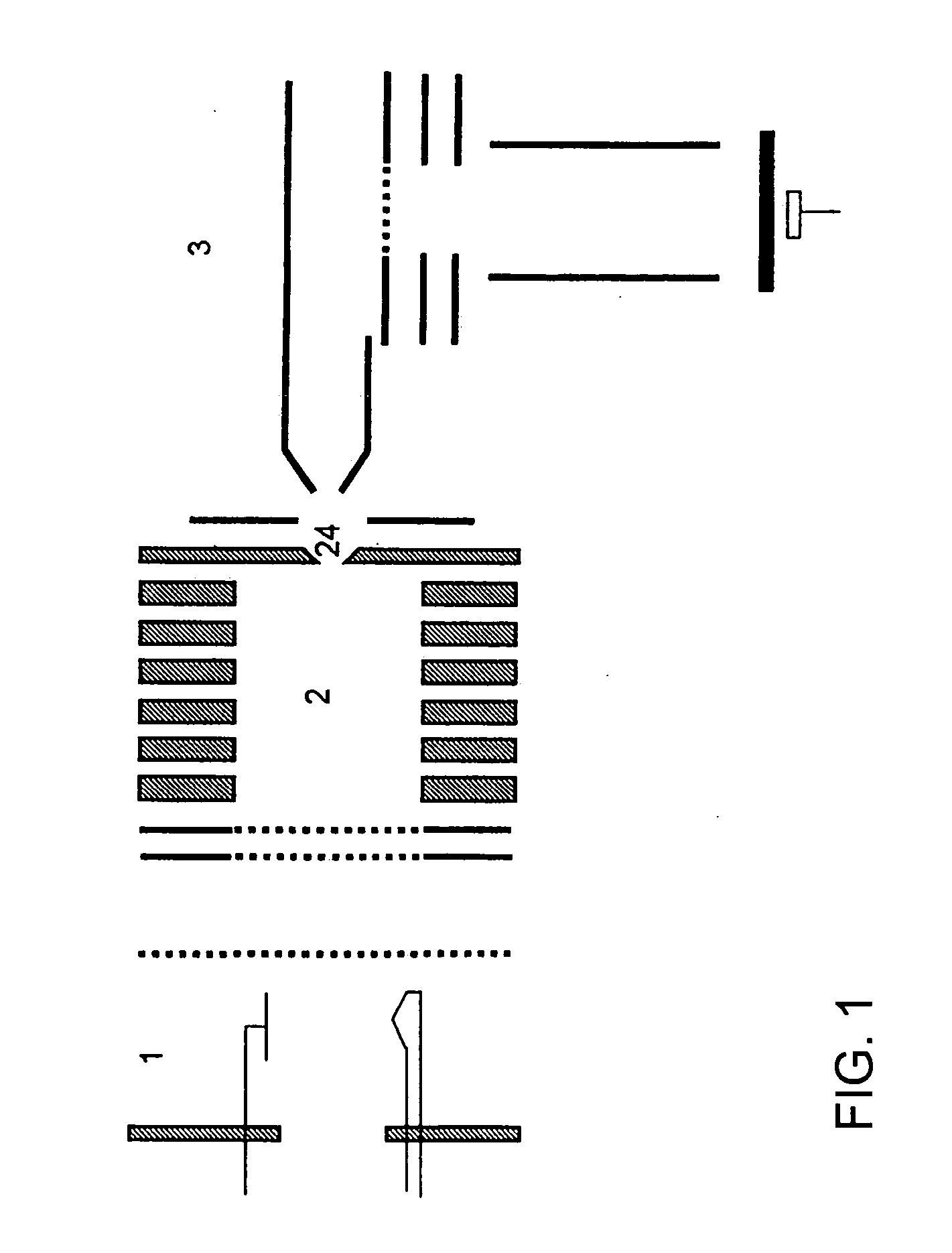
[0025] The invention described herein has the goal of improving the general instrumental design and, as a result, the analytical performance of ion mobility instruments. This aspect of the present invention is focused on enhanced analytical performance, which results from using the improvements in the components of the instrumentation. These improvements primarily lie in the various electrode configurations and conformations. In a specific embodiment of the present invention, an apparatus and method for performing ion mobility spectrometry uses an ionization source, a drift cell and a detector. It also uses a parallel electrode assembly comprising a component of at least one field correcting ring electrode or at least one movable cylindrical electrode or at least one radius of curvature electrode. Preferably, matrix-assisted laser desorption ionization is used to ionize samples. Alternatively, electrospray ionization, a laser ionization, a photoionization, electron ionization, chemical ionization, an electric field ionization, surface ionization, radioactive ionization, discharge ionization and / or a multiphoton ionization may be used to ionize sample.

Problems solved by technology

The challenging issue when building a Mobility-MS is achieving a high ion transmission from the mobility region into the MS region of the tandem instrument.
As discussed above, in the early development of IMS, it was believed that the use of focusing methods (i.e., non-linear fields) was detrimental because it was believed that such focusing methods would deteriorate the resolution of the mobility spectrometer.
All of these methods have drawbacks associated with their construction and ease of implementation.

Method used


Image

  • Ion mobility spectrometer
  • Ion mobility spectrometer
  • Ion mobility spectrometer

Examples


Embodiment Construction

[0067] As used herein, “drift tube diameter” is defined as the distance from the spectrometer axis to the electrode surface nearest to the spectrometer axis. In the case of multiple coaxial series of electrodes, this distance refers to that from the spectrometer axis to the electrode surface nearest to the spectrometer axis of the innermost coaxial series of electrodes. It is synonymous with the expression “inner diameter”.

[0068] As used herein, a “combination” of periodic field focussing and hyperbolic field focusing in an ion drift cell is any coexistence of the two types of fields in the drift cell; they may be sequential to one another (i.e., serial; and in any order) or be superimposed (i.e., a superposition) on one another. It may also include multiple field regions in the drift cell. It may also include one or more regions of a superposition and one or more other regions of a sequential combination.

[0069] As used herein, “electrode width” is defined as the ratio of the leng...


PUM


Abstract

The present invention relates to an improved ion mobility spectrometer and method for the analysis of chemical samples. The improvements are realized in the optimization of resolution and sensitivity. Increases in sensitivity are realized by preserving a narrow spatial distribution of migrating ions through the use of periodic / hyperbolic field focusing. Use of a plurality of drift cells and a new RF field focusing interface are discussed.

Description

[0001] This application is a continuation-in-part of, and claims priority to U.S. application Ser. No. 09 / 798,030, filed Feb. 28, 2001, which claims priority to U.S. Provisional Application No. 60 / 193,659, filed Mar. 31, 2000, and to U.S. Provisional Application No. 60 / 185,781, filed Feb. 29, 2000.STATEMENT REGARDING FEDERALLY SPONSORED RESEARCH OR DEVELOPMENT [0002] The technology was developed with government support The government may have certain rights in the invention.TECHNICAL FIELD [0003] The present invention relates generally to instrumentation and methodology for characterization of chemical samples based on improved ion mobility spectrometry (IMS) instrumentation. The improvements are also incorporated into a mobility-mass spectrometer, which is a tandem configuration of an ion mobility spectrometer (IMS) and a mass spectrometer (MS). This apparatus is an instrument for qualitative and / or quantitative chemical and biological analysis. BACKGROUND OF THE INVENTION [0004] A...

Claims


Application Information

Patent Timeline
IPC IPC(8): G01N27/64
CPCG01N27/622H01J49/40H01J49/004H01J49/401G01N27/623
Inventor FUHRER, KATRINGONIN, MARCSCHULTZ, J. A.
Owner IONWERKS
Learn More