Arrayed wavelength converter

a wavelength converter and wavelength technology, applied in multiplex communication, instruments, optical elements, etc., can solve the problems of expensive cost, incongruity of output power after wavelength conversion among wavelengths, and difficulty in all wavelengths, and achieve the effect of simple structure and highly efficient wavelength conversion

Inactive Publication Date: 2005-09-01
FUJITSU LTD
View PDF1 Cites 16 Cited by
  • Summary
  • Abstract
  • Description
  • Claims
  • Application Information

AI Technical Summary

Benefits of technology

[0012] The present invention has been accomplished in view of the above problems, and has an object to provide an arrayed wavelength converter with a simple structure, which enables highly efficient wavelength conversion, by either selecting optical signals of a plurality of wavelengths collectively, or selecting only an arbitrary wavelength.

Problems solved by technology

However, with the abovementioned wavelength conversion in accordance with the quasi-phase matching method using the polarization inversion structure, in the case where the wavelength conversion of optical signals of a plurality of wavelengths is performed using the polarization reversal structure with a single waveguide and a single period, it becomes difficult for all of the wavelengths to satisfy a phase matching condition expressed in the following equation (1).
Therefore, there is a problem in that, for example as shown in FIG. 15, the output power after wavelength conversion becomes inconsistent among the wavelengths.
However, with such a wavelength conversion circuit, since the number of cascade connections of wavelength conversion units is increased and the number of components is increased, as the number of wavelengths of optical signals to be subjected to the wavelength conversion is increased, there is a disadvantage of expensive cost.

Method used


Image

  • Arrayed wavelength converter
  • Arrayed wavelength converter
  • Arrayed wavelength converter

Examples


Embodiment Construction

[0036] Hereunder is a description of embodiments for implementing an arrayed wavelength converter of the present invention, with reference to the appended drawings. Throughout the drawings, the same reference numerals denote the same or equivalent parts.

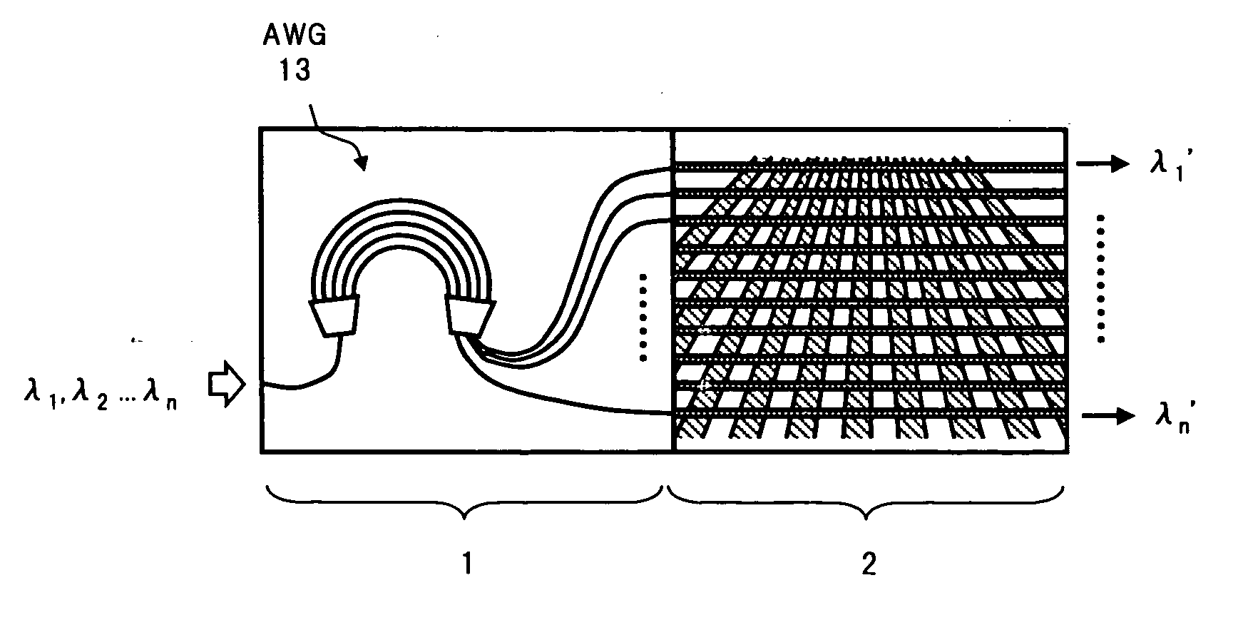
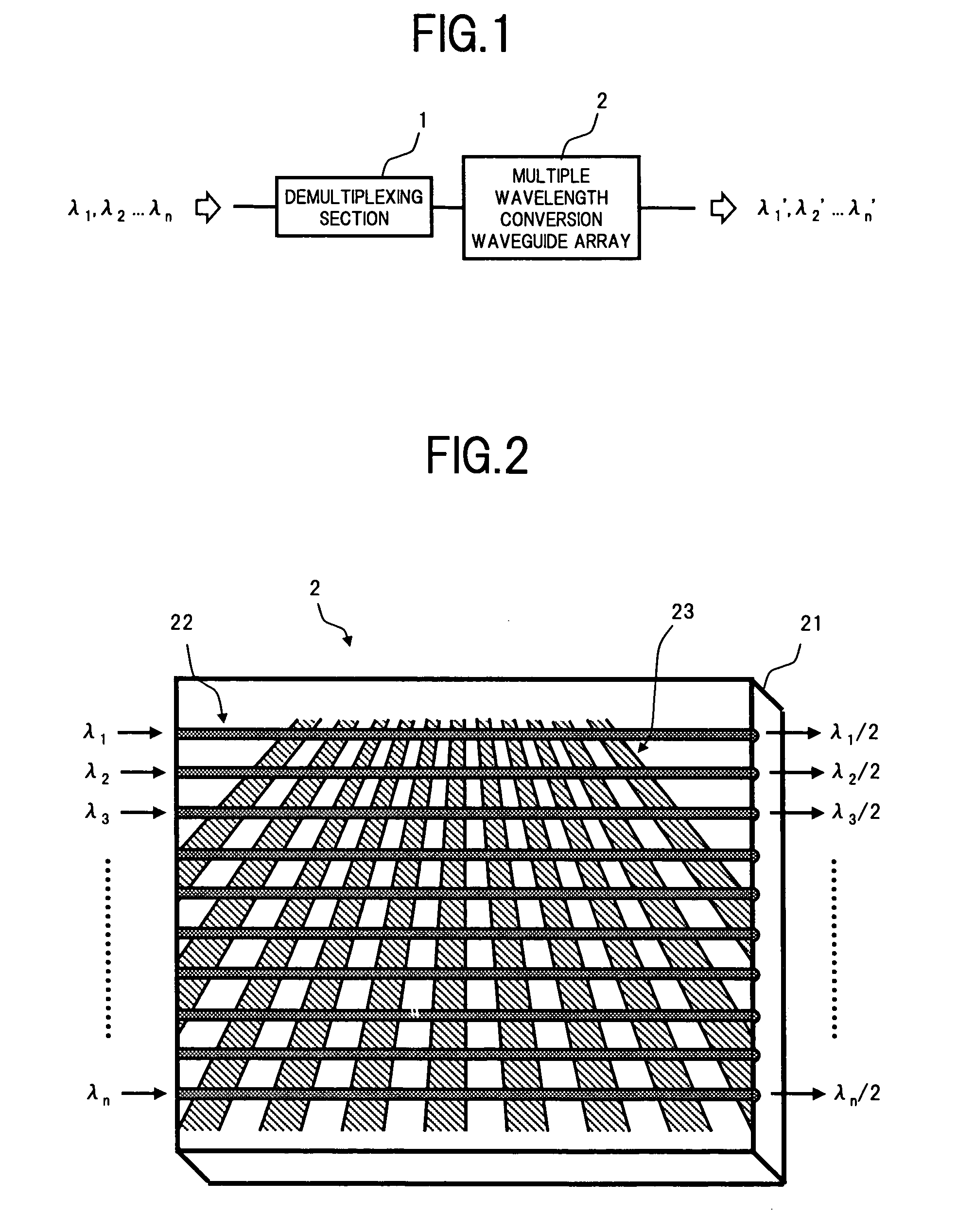
[0037]FIG. 1 is a functional block diagram showing a configuration of an arrayed wavelength converter according to one embodiment of the present invention.

[0038] In FIG. 1, the arrayed wavelength converter of the present embodiment comprises, for example, a demultiplexing section 1 to which a WDM signal light containing optical signals of a plurality of wavelengths, λ1, λ2 to λn, are input, and a multiple wavelength conversion waveguide array 2 to which is given optical signals of respective wavelength λ1′, to λn′ output from the demultiplexing section 1.

[0039] The demultiplexing section 1 is for demultiplexing the input WDM signal light corresponding to wavelengths, to output demultiplexed lights, and can be constructed using a k...


PUM

PropertyMeasurementUnit
wavelengthsaaaaaaaaaa

Abstract

An arrayed wavelength converter comprises a demultiplexing section that demultiplexes an input WDM signal light to output the demultiplexed lights, and a multiple wavelength conversion waveguide array in which the optical signals of respective wavelengths output from the demultiplexing section are given respectively to a plurality of waveguides formed in parallel on a substrate made of ferroelectric crystal. The multiple wavelength conversion waveguide array has a periodic polarization structure formed by periodically providing polarization inversion regions in which a polarization direction of the substrate is inversed, in a direction approximately perpendicular to a traveling direction of lights being propagated along the respective waveguides, and this is set such that a period of the periodic polarization structure is made different for each waveguide. As a result, it becomes possible to perform wavelength conversion of a plurality of optical signals at high efficiency with a simple structure.

Description

BACKGROUND OF THE INVENTION [0001] (1) Field of the Invention [0002] The present invention relates to a wavelength converter, which converts an input optical signal into an optical signal of a different wavelength to output the converted optical signal, and in particular, relates to an arrayed wavelength converter capable of performing wavelength conversion collectively on wavelengths of optical signals of a plurality of wavelengths. [0003] (2) Description of the Related Art [0004] As one technique for increasing transmission capacity of a communication using optical fibers, there is a wavelength division multiplexing (WDM) system. In an optical communication system to which the WDM system is applied, a plurality of optical carriers having different wavelengths is used. A plurality of optical signals obtained by independently modulating each optical carrier, is multiplexed by an optical multiplexer, and a WDM signal light obtained as a result, is sent out to an optical fiber transmi...

Claims


Application Information

Patent Timeline
Patent Type & Authority Applications(United States)
IPC IPC(8): G02B6/34G02F1/377H04J14/00H04J14/02
CPCG02B6/12019H04J14/02G02B6/12023
Inventor MARUYAMA, SHINJIMATSUDA, RUMIKO
Owner FUJITSU LTD
Why Eureka
Try Eureka