Fuel cut control apparatus of internal combustion engine

a control apparatus and internal combustion engine technology, applied in mechanical devices, electric control, machines/engines, etc., can solve the problem of bringing oxygen in the exhaust gas into an excessive state, and achieve the effect of suppressing the generation of exhaust odor and preventing the deterioration of the exhaust gas purifying catalys

Inactive Publication Date: 2005-09-08
TOYOTA JIDOSHA KK
View PDF14 Cites 25 Cited by
  • Summary
  • Abstract
  • Description
  • Claims
  • Application Information

AI Technical Summary

Benefits of technology

[0009] The present invention is made to solve the above problems, and its object is to provide a fuel cut control apparatus of an internal combustion engine which makes it possible to properly perform fuel cut with preventing deterioration of an exhaust gas purifying catalyst and suppressing generation of exhaust odor.

Problems solved by technology

Thus, the fuel cut control apparatus of an internal combustion engine includes the maximum oxygen storage amount obtaining unit which obtains the maximum oxygen storage amount of the exhaust gas purifying catalyst, and when the maximum oxygen storage amount is equal to or larger than a predetermined amount, the fuel cut control apparatus executes fuel cut and brings oxygen in the exhaust gas into an excessive state.

Method used


Image

  • Fuel cut control apparatus of internal combustion engine
  • Fuel cut control apparatus of internal combustion engine
  • Fuel cut control apparatus of internal combustion engine

Examples


first embodiment

[0036] First, fuel cut processing according to a first embodiment of the present invention will be explained with reference to a flow chart in FIG. 4. The fuel cut processing according to the first embodiment intends to perform fuel cut while suppressing generation of H2S causing exhaust odor and preventing deterioration of the exhaust gas purifying catalyst. The fuel cut processing is executed by the ECU 20 controlling a fuel injection valve (not shown) in the engine 1 and making the fuel injection rate zero. The fuel cut processing explained below is repeatedly carried out at predetermined cycles during operation of the engine 1.

[0037] The ECU 20 firstly determines whether a present number of engine revolution NE is equal to or higher than a predetermined number of engine revolution NE0 or not in step S11. The ECU 20 obtains the number of engine revolution NE from the signal S2 outputted from the engine 1. The predetermined number of engine revolution NE0 is stored in a memory or...

second embodiment

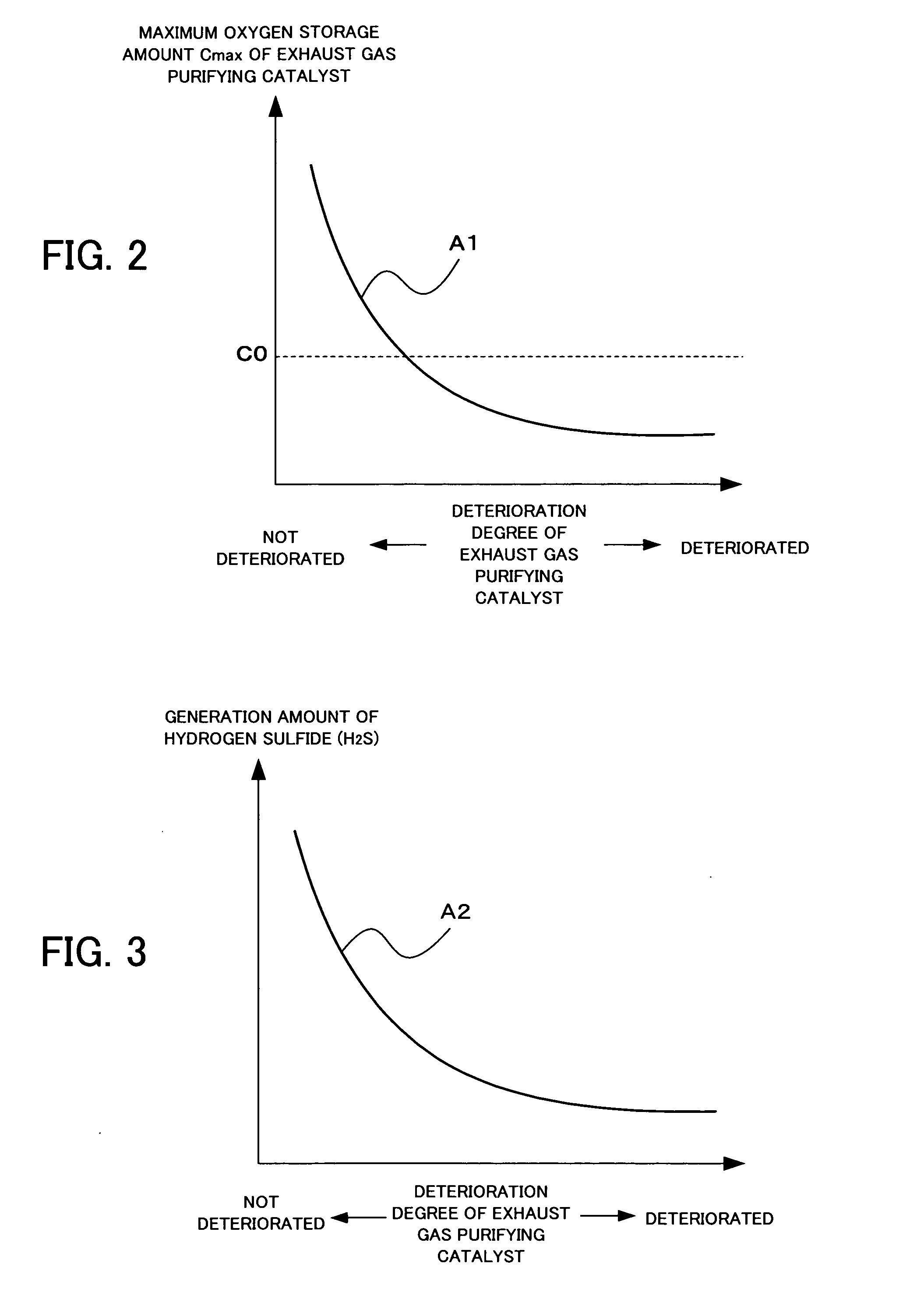
[0053] Fuel cut processing according to a second embodiment also performs fuel cut in consideration of the maximum oxygen storage amount Cmax of the exhaust gas purifying catalyst 3 and the temperature T of the exhaust gas purifying catalyst 3 as in the fuel cut processing according to the first embodiment. However, in the fuel cut processing according to the second embodiment, when the maximum oxygen storage amount Cmax of the exhaust gas purifying catalyst 3 is equal to or larger than the predetermined amount C0, the fuel cut is performed only in the necessary range for preventing the generation of the exhaust odor, and thereby the deterioration of the catalyst is prevented. The fuel cut processing according to the second embodiment will be explained hereinafter by using a flow chart shown in FIG. 5. The fuel cut processing is performed mainly by the ECU 20.

[0054] The processing in step S20 and step S21 are the same as the processing in step S11 and step S12 shown in FIG. 4. Name...

modification example

[0064] A modification example concerning the fuel cut processing of the above-described second embodiment will be explained. The fuel cut processing according to the modification example will be shown in FIG. 6.

[0065]FIG. 5 showing the fuel cut processing according to the second embodiment differs from FIG. 6 showing the fuel cut processing according to the modification example only in the processing of the case in which the temperature T of the exhaust gas purifying catalyst 3 is lower than the predetermined temperature T0 (step S27; Yes and step S37; Yes). In the second embodiment, the target time TFC0 in which the fuel cut is continued is calculated only when the maximum oxygen storage amount Cmax of the exhaust gas purifying catalyst 3 is equal to or larger than the predetermined amount C0 (step S22; Yes), but in the modification example, the ECU 20 also calculates the target time TFC0 in step S33 when the temperature T of the exhaust gas purifying catalyst 3 is lower than the ...


PUM


Abstract

The exhaust gas purifying catalysts sometimes generate H2S which emits exhaust odor under reducing atmosphere. However, in the ordinary air-fuel ratio control, it takes much time to establish sufficient oxygen atmosphere for suppressing H2S emission when the maximum oxygen storage amount which the exhaust gas purifying catalyst can store is large. Thus, the fuel cut control apparatus of an internal combustion engine executes fuel cut to bring oxygen in the exhaust gas into an excessive state when the maximum oxygen storage amount is a predetermined amount or more. As a result, sufficient oxygen can be stored in the exhaust gas purifying catalyst. Even when the maximum oxygen storage amount of the exhaust gas purifying catalyst is smaller than the predetermined amount, if the temperature of the exhaust gas purifying catalyst is lower than predetermined temperature, fuel cut is executed. In this case, influence which is given to deterioration of the catalysts is small even if the fuel cut is executed and the inside of the catalysts is under the oxygen atmosphere. On the other hand, if the temperature of the exhaust gas purifying catalyst is the predetermined temperature or higher, the fuel cut is not executed. Since the deterioration of the catalyst is promoted when the catalyst is under the oxygen atmosphere at high temperature, priority is given to prevention of deterioration of the exhaust gas purifying catalyst.

Description

BACKGROUND OF THE INVENTION [0001] 1. Field of the Invention [0002] The present invention relates to a fuel cut control apparatus of an internal combustion engine. [0003] 2. Description of the Related Art [0004] In an exhaust gas purifying catalyst (hereinafter, also simply called “catalyst”) such as a three-way catalyst which is placed in an exhaust passage of a vehicle, sulfur (S) is adsorbed by ceria (CeO2) in the catalyst when an air-fuel ratio is lean, and when it is rich, the sulfur is desorbed. It is known that the desorbed sulfur oxide (SO2) is reduced and hydrogen sulfide (H2S) is generated. The H2S has such an odor that gives a discomfort to a driver (hereinafter, called “exhaust odor”). [0005] As a control technique concerning suppression of H2S, for example, Japanese Patent Application Laid-Open under No. 2003-65127 discloses the art of suppressing the generation of the above-described H2S by controlling the air-fuel ratio to be lean (namely, to establish oxidation atmos...

Claims


Application Information

Patent Timeline
Patent Type & Authority Applications(United States)
IPC IPC(8): F01N3/24F01N3/00F01N3/28F02D41/12
CPCF01N3/101F02D41/0295F02D41/123F02D2200/0404F01N13/009F02D2200/0814F02D2200/101Y02T10/22F02D2200/0802Y02T10/12
Inventor FUJIWARA, TAKAHIKONAKATA, KUNIHIKOICHINOSE, HIROKIHIRATA, ATSUNORI
Owner TOYOTA JIDOSHA KK
Why Eureka
Try Eureka