Structure of engine starter equipped with planetary gear speed reducer
- Summary
- Abstract
- Description
- Claims
- Application Information
AI Technical Summary
Benefits of technology
Problems solved by technology
Method used
Image
Examples
first embodiment
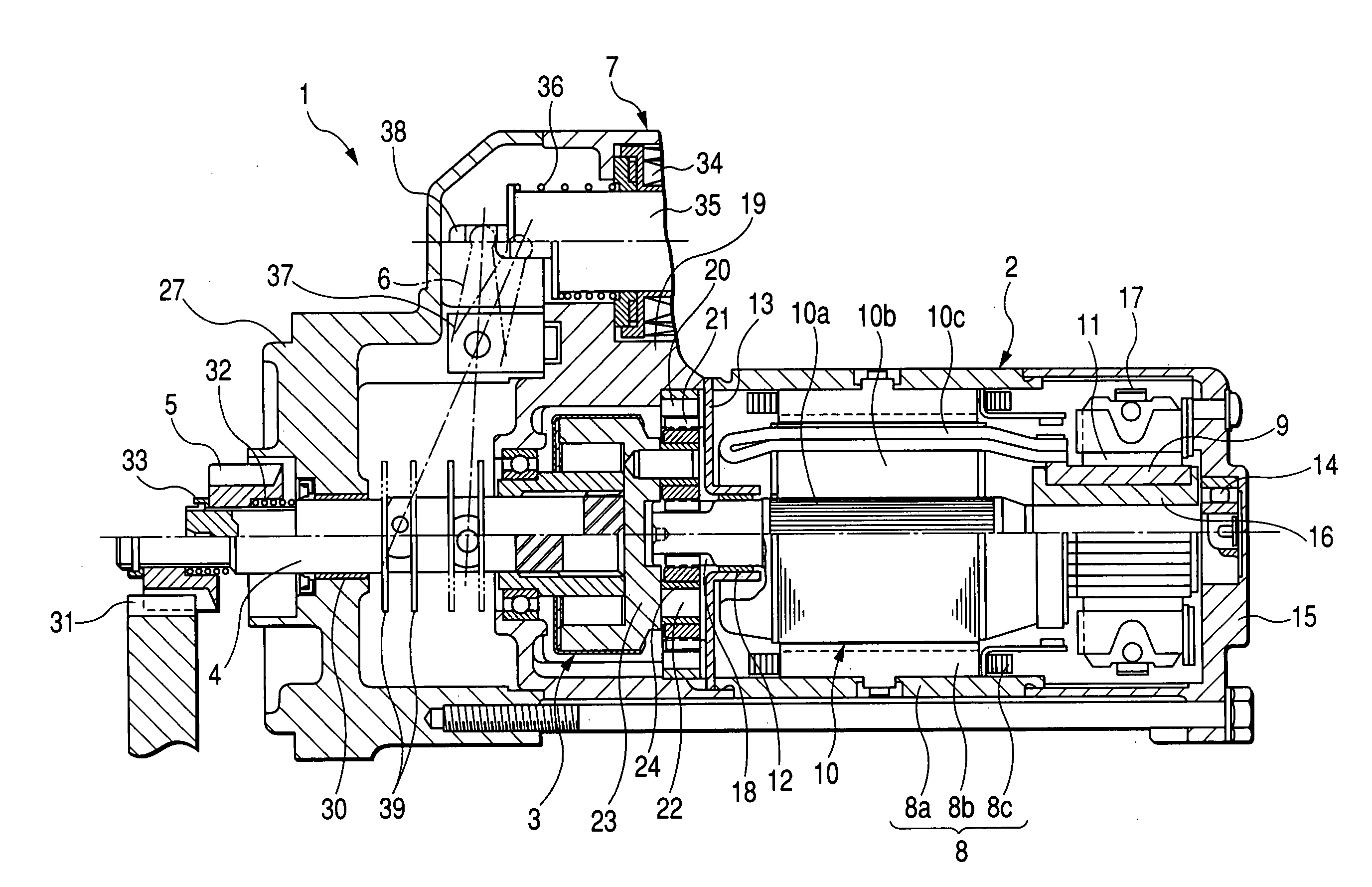
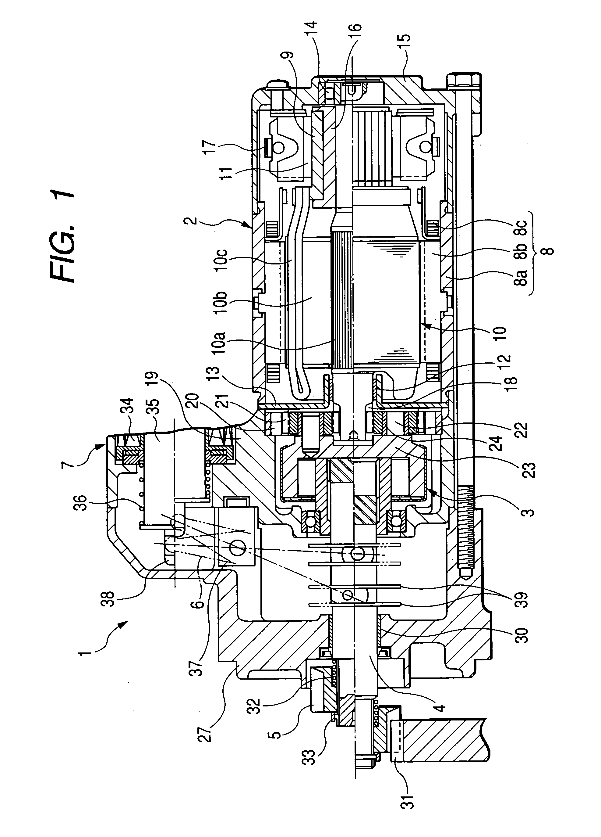
[0048] Referring to the drawings, wherein like reference numbers refer to like parts in several views, particularly to FIG. 1, there is shown a starter 1 according to the invention which may be employed in starting an automotive engine.
[0049] The starter 1 consists essentially of an electric motor 2, a speed reduction mechanism, as will be described later in detail, an output shaft 4, a pinion gear 5, and a solenoid switch 7. An output of the motor 2 is reduced in speed by the speed reduction mechanism and transmitted to the output shaft 4 through a one-way clutch (also called an overrunning clutch) 3. The output shaft 4 has the pinion gear 5 fitted thereon. The solenoid switch 7 works to close main contacts (not shown) installed in a driver circuit of the motor 2 and advance the output shaft 4 in an axial direction thereof through a shift lever 6.
[0050] The motor 2 is a dc motor which includes a field system 8, an armature 10 with a commutator 9, and brushes 11 riding on the commu...
second embodiment
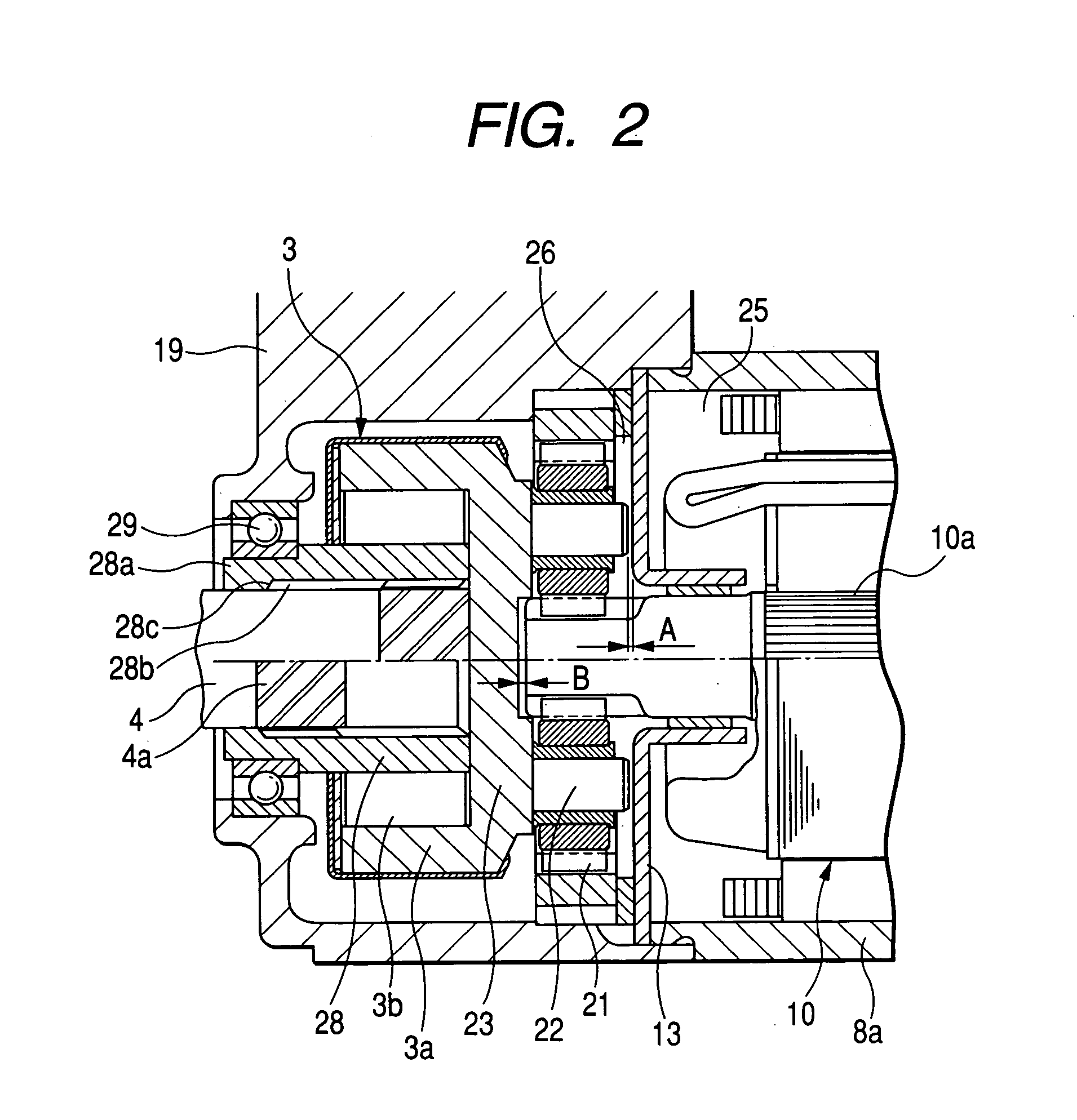
[0076]FIG. 3 shows the speed reduction mechanism and periphery thereof the starter 1 according to the invention.
[0077] The starter 1 has an annular plate 40 disposed on the outer wall of the partition plate 13 within the speed reducer chamber 26 so that the tips of the support pins 22 may abut directly on the plate 40. Specifically, the plate 40 works to sustain the thrust loads exerted by the support pins 22. The plate 40 is greater in surface hardness than the partition plate 13 and held directly by the partition plate from rotating. This eliminates the need for thermal treatment of the partition plate 13, thus permitting the partition plate 13 to be made of an untreated material, resulting in decreased costs of the starter 1.
[0078] The plate 40 is held by the partition plate 13 from rotating following orbital motion of the support pins 22 around the armature shaft 10a, so that the frictional pressures between the support pins 22 and the plate 40 produces a sufficient amount of b...
third embodiment
[0086]FIG. 4 shows the speed reduction mechanism and periphery thereof the starter 1 according to the invention.
[0087] The carrier 23 has a cone-shaped tapered recess 23a from in the center of the rear end wall thereof. Similarly, the armature shaft 10a has a cone-shaped tapered recess 10d formed in the center of the front end thereof in alignment with the tapered recess 23a of the carrier 23 along the axis of the starter 1. A ball 44 is interposed between the tapered recesses 23a and 10d. This structure works to center the outer 3a of the one-way clutch 3 to the armature shaft 10a. At the overrun of the one-way clutch 3 caused by transmission of the engine torque the pinion gear 5 after the start-up of the engine, the rollers 3b are usually lifted from the tube 28 (i.e., the inner), which allows the outer 3a to be moved eccentrically in a radius direction, as indicated by an arrow in the drawing. The ball 44, however, works to hold the outer 3a from moving in the radius direction a...
PUM
 Abstract
Description
Claims
Application Information
 - R&D
- Intellectual Property
- Life Sciences
- Materials
- Tech Scout
- Unparalleled Data Quality
- Higher Quality Content
- 60% Fewer Hallucinations
Browse by: Latest US Patents, China's latest patents, Technical Efficacy Thesaurus, Application Domain, Technology Topic, Popular Technical Reports.
© 2025 PatSnap. All rights reserved.Legal|Privacy policy|Modern Slavery Act Transparency Statement|Sitemap|About US| Contact US: help@patsnap.com


