Substrate support system for reduced autodoping and backside deposition

a technology of backside deposition and substrate support, which is applied in the direction of chemically reactive gases, coatings, crystal growth processes, etc., can solve the problems of direct impingement of relatively focused, limited conventional substrate support methods and systems, and high velocity flows of purge gas onto the substrate, etc., to facilitate gas flow, facilitate gas flow, facilitate the effect of gas flow

Active Publication Date: 2005-09-08
ASM IP HLDG BV
View PDF47 Cites 226 Cited by
  • Summary
  • Abstract
  • Description
  • Claims
  • Application Information

AI Technical Summary

Benefits of technology

[0017] In one aspect, the present invention provides a substrate support system comprising a substrate holder for holding a substrate. The substrate holder comprises a central portion, at least one spacer extending upward from the central portion, and a hollow support member. The central portion has an upper surface, a lower surface, and a plurality of open passages extending from the upper surface to the lower surface. The at least one spacer has an upper support surface raised above the upper surface of the central portion. The at least one spacer's upper support surface is configured to support a peripheral portion of the substrate so that a gap region exists between the upper surface of the central portion and a bottom surface of the substrate. The hollow support member has an inlet adapted to engage an outlet of a gas-conveyor to facilitate gas flow from the gas-conveyor into the hollow support member. The hollow support member also has one or more upper open ends adapted to support the lower surface of the central portion of the substrate holder. The one or more upper open ends are configured to convey gas upward into lower ends of one or more of the passages in the central portion of the substrate holder. At least one of the passages has a lower end open to a region that is not inside the hollow support member.
[0018] In another aspect, the present invention provides a substrate support system comprising a substrate holder for holding a substrate, and a hollow support spider. The substrate holder comprises a central portion and a plurality of spacers extending upward therefrom. The central portion has an upper surface, a lower surface, and a plurality of passages extending from the upper surface to the lower surface. The spacers have upper support surfaces raised above the upper surface of the central portion. The spacers' upper support surfaces are configured to support a peripheral portion of the substrate so that a gap region exists between the upper surface of the central portion and a bottom surface of the substrate. The support spider comprises a hollow manifold and a plurality of hollow arms extending generally radially outward and upward therefrom. The manifold has an inlet adapted to engage an outlet of a gas-conveyor to facilitate gas flow from the gas-conveyor into the manifold. The hollow arms are configured to receive gas flow from the manifold. The hollow arms have open upper ends adapted to support the lower surface of the central portion of the substrate holder. The open upper ends of the hollow arms are configured to convey gas upward into a subset of the passages of the central portion of the substrate holder.
[0019] In another aspect, the present invention provides a substrate support system comprising a substrate holder for holding a substrate, and a hollow support member. The substrate holder comprises a generally planar central portion and a plurality of spacers extending upward therefrom. The central portion has an upper surface, a lower surface, and a plurality of open passages extending from the upper surface to the lower surface. The spacers have upper support surfaces raised above the upper surface of the central portion. The spacers' upper support surfaces are configured to support a peripheral portion of the substrate so that a gap region exists between the upper surface of the central portion and a bottom surface of the substrate. The hollow support member comprises a lower base member and an annular wall extending upward therefrom. The base member has an inlet adapted to engage an outlet of a gas-conveyor to facilitate gas flow from the gas-conveyor into the hollow support member. The annular wall has an upper edge configured to support a bottom surface of the substrate holder so that gas within the annular wall and between the base member and the bottom surface of the substrate holder is substantially prevented from flowing between the upper edge of the annular wall and the bottom surface of the substrate holder. The upper edge of the annular wall defines an upper opening of the hollow support member. This upper opening is configured to convey gas upward into lower ends of at least 10 of the passages of the central portion of the substrate holder.
[0020] In another aspect, the present invention provides a substrate holder for holding a substrate, comprising a central portion and a plurality of spacers extending upward therefrom. The central portion has an upper surface, a lower surface, a first set of open passages extending from the upper surface to the lower surface, and a second set of open passages each extending from the upper surface to one of a plurality of recesses within the lower surface. Each of the recesses is adapted to receive one of a plurality of corresponding upper ends of tubular arms of a hollow support member configured to support the central portion and convey gas upward into the second set of passages. The spacers have upper support surfaces raised above the upper surface of the central portion. The spacers' upper support surfaces are configured to support a peripheral portion of the substrate so that a gap region exists between the upper surface of the central portion and a bottom surface of the substrate.
[0021] In yet another aspect, the present invention provides a hollow support member for supporting a substrate holder that is in turn configured to support a substrate during substrate processing. The hollow support member comprises a base member and an annular wall extending upward therefrom. The base member has a lower inlet adapted to engage an upper end of a hollow tube to facilitate upward gas flow from the tube into the hollow support member. The annular wall has an upper edge configured to support a bottom surface of the substrate holder so that gas within the annular wall and between the base member and the bottom surface of the substrate holder is substantially prevented from flowing between the upper edge of the annular wall and the bottom surface of the substrate holder. The upper edge defines an upper opening of the hollow support member. The upper opening defines an area of at least 70% of the size of a substrate that the substrate holder is specifically designed to support.
[0022] In yet another aspect, the present invention provides a method of processing a substrate. The method involves a substrate holder comprising a generally planar central portion and a plurality of spacers extending upward therefrom. The central portion has an upper surface, a lower surface, and plurality of passages extending from the upper surface to the lower surface. The spacers have upper support surfaces raised above the upper surface of the central portion. The spacers' upper support surfaces are configured to support a peripheral portion of a substrate so that a gap region exists between the upper surface of the central portion and a bottom surface of the substrate. According to the method, the substrate holder is provided and then a substrate is rested thereon so that the spacers' upper support surfaces support a peripheral portion of the substrate. An upward flow of gas is directed directly into lower ends of one or more selected ones of the passages so that the gas flows into the gap region. Lower ends of a remaining one or more passages of the substrate holder are left open.

Problems solved by technology

Conventional substrate support methods and systems for preventing backside deposition and autodoping are somewhat limited.
These channels often result in the direct impingement of relatively focused, high velocity flows of purge gas onto the substrate backside.
This can cause localized cooling or “cold spots” in the substrate, which adversely affects the uniformity of deposited materials on the substrate.
Also, conventional purge gas systems are typically not designed to prevent autodoping.
Conversely, conventional systems for preventing autodoping are typically not designed to prevent backside deposition of reactant gases.
Unfortunately, it is often very difficult to effect a completely fluid-tight separation between the regions above and below the substrate holder.
Thus, there is a significant risk of deposition of reactant gases on the substrate backside.

Method used


Image

  • Substrate support system for reduced autodoping and backside deposition
  • Substrate support system for reduced autodoping and backside deposition
  • Substrate support system for reduced autodoping and backside deposition

Examples


Embodiment Construction

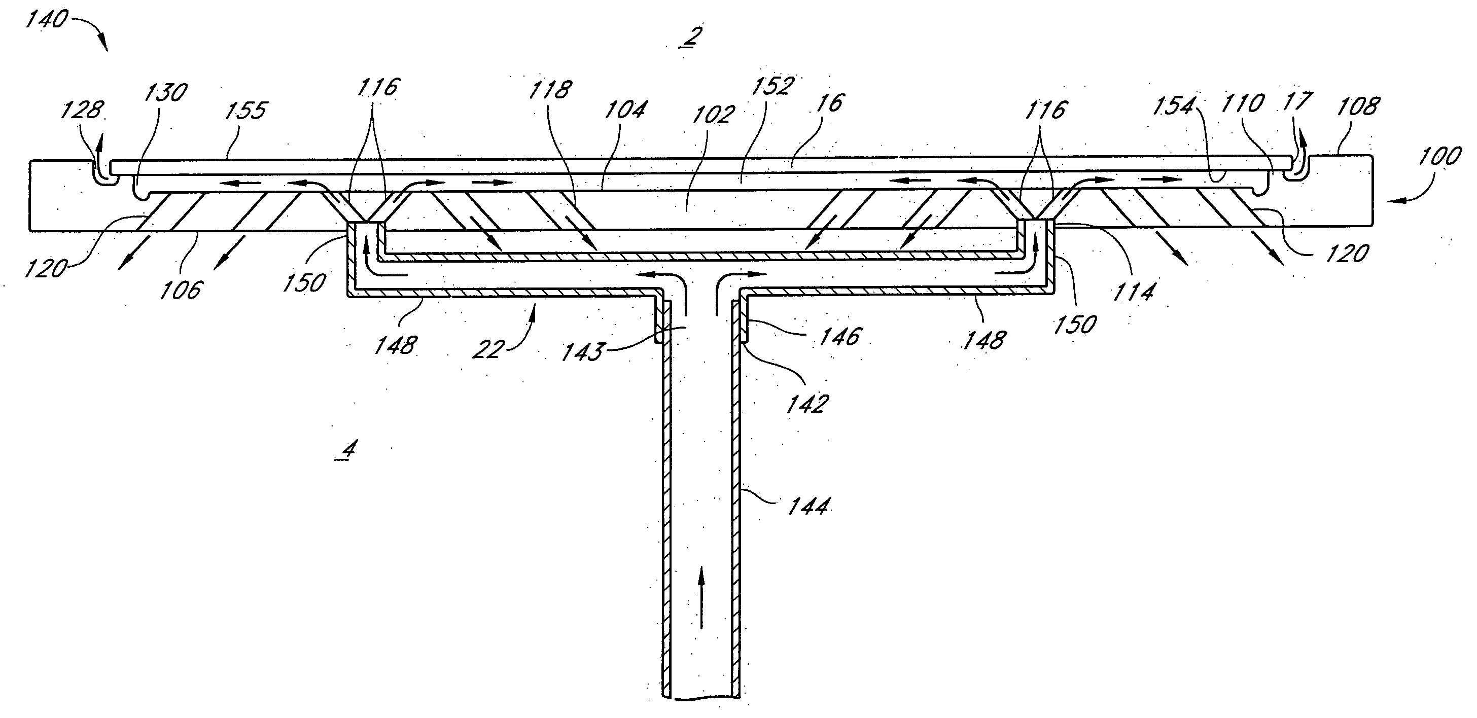
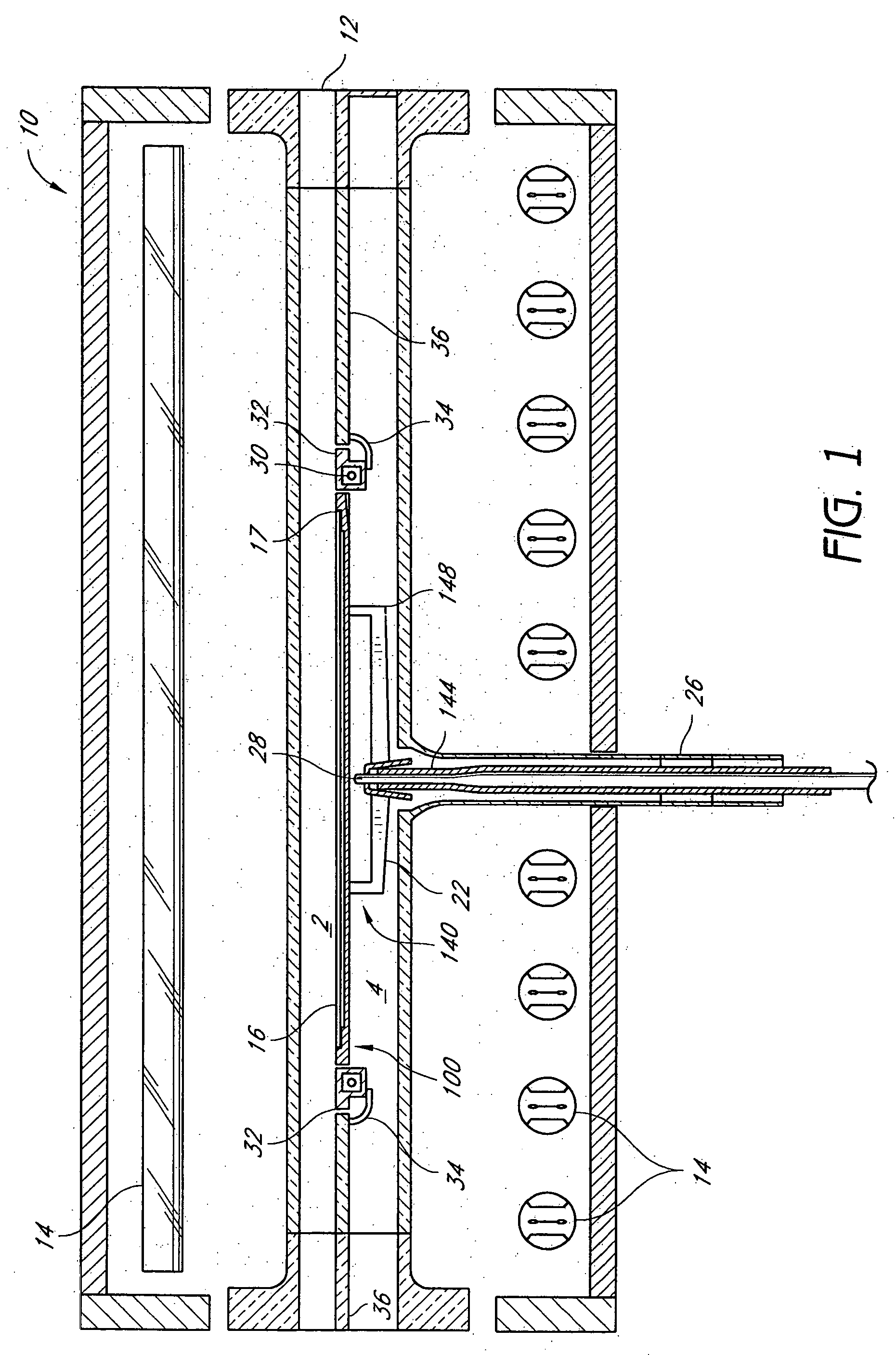
[0038] Prior to describing the substrate holder of the invention, an exemplary CVD reactor is disclosed. FIG. 1 illustrates an exemplary CVD reactor 10, including a quartz reaction chamber 12. Radiant heating elements 14 are supported outside the transparent chamber 12, to provide heat energy to the chamber 12 without appreciable absorption by the chamber walls. Although the preferred embodiments are described in the context of a “cold wall” CVD reactor, it will be understood that the substrate support systems described herein can be used in other types of reactors and semiconductor processing equipment. Skilled artisans will appreciate that the claimed invention is not limited to use within the particular reactor 10 disclosed herein. In particular, one of skill in the art can find application for the substrate support systems described herein for other semiconductor processing equipment, wherein a substrate is supported while being uniformly heated or cooled. Moreover, while illust...


PUM

PropertyMeasurementUnit
angleaaaaaaaaaa
diameteraaaaaaaaaa
diameteraaaaaaaaaa

Abstract

A substrate support system comprises a relatively thin circular substrate holder having a plurality of passages extending between top and bottom surfaces thereof. The substrate holder includes a single substrate support ledge or a plurality of substrate support spacer vanes configured to support a peripheral portion of the substrate backside so that a thin gap is formed between the substrate and the substrate holder. The vanes can be angled to resist backside deposition of reactant gases as the substrate holder is rotated. A hollow support member provides support to an underside of the substrate holder. The hollow support member is configured to convey gas (e.g., inert gas or cleaning gas) upward into one or more of the passages of the substrate holder. The upwardly conveyed gas flows into the gap between the substrate and the substrate holder. Depending upon the embodiment of the invention, the gas in the gap can then flow either (1) outward and upward around the substrate edge or (2) downward through passages of the substrate holder, if any, that do not lead back into the hollow support member. The gas that flows outward and upward around the substrate edge inhibits backside deposition of reactant gases above the substrate. The gas that flows downward through the passages that do not lead back to the support member advantageously inhibits autodoping by sweeping out-diffused dopant atoms away from the substrate front side. In one embodiment, the support member comprises a hollow multi-armed support spider that conveys gas into selected ones of the passages. In another embodiment, the support member comprises a bowl- or cup-shaped structure that conveys gas upward into all of the passages. In yet another embodiment, the support member comprises a bowl- or cup-shaped structure that conveys gas upward into all but one or more of the passages.

Description

CLAIM FOR PRIORITY [0001] This application claims priority under 35 U.S.C. § 119(e) to Provisional Patent Application Ser. No. 60 / 545,181 to Goodman et al., filed Feb. 13, 2004, and Provisional Patent Application Ser. No. 60 / 591,258 to Stoutyesdijk et al., filed Jul. 26, 2004.INCORPORATION BY REFERENCE [0002] This application hereby incorporates by reference the entire disclosures of U.S. Pat. No. 6,093,252; Nonprovisional patent application Ser. No. 10 / 697,401 to Keeton et al., filed Oct. 29, 2003; Provisional Patent Application Ser. No. 60 / 545,181 to Goodman et al., filed Feb. 13, 2004; and Provisional Patent Application Ser. No. 60 / 591,258 to Stoutyesdijk et al., filed Jul. 26, 2004. BACKGROUND OF THE INVENTION [0003] 1. Field of the Invention [0004] The present invention relates generally to semiconductor processing equipment and specifically to systems and methods for supporting a substrate during material deposition processes. [0005] 2. Description of the Related Art [0006] Hi...

Claims


Application Information

Patent Timeline
Patent Type & Authority Applications(United States)
IPC IPC(8): C23C16/00C23C16/458C30B25/12C30B25/14H01L21/00H01L21/687
CPCH01J37/32871H01L21/68735H01L21/67028H01L21/683
Inventor GOODMAN, MATT G.STOUTYESDIJK, JEREONAGGARWAL, RAVINDERHALPIN, MIKEKEETON, TONYHAWKINS, MARKHAEN, LEEFERRO, ARMANDBRABANT, PAULVYNE, ROBERTBARTLETT, GREGORY M.ITALIANO, JOSEPH P.HARO, BOB
Owner ASM IP HLDG BV
Why Eureka
Try Eureka