
Variable compliance joystick with compensation algorithms

a compensation algorithm and joystick technology, applied in the field of electric powered wheelchair custom control, can solve the problems of slow and awkward wheelchair control system, insufficient joystick for as many as 40% of potential wheelchair users, and no commercial position sensing joystick control suitable, so as to reduce the bendable length of the lower joystick segment, and vary the compliance of the shaft

Inactive Publication Date: 2005-09-08
COOPER RORY A +2
View PDF33 Cites 45 Cited by
  • Summary
  • Abstract
  • Description
  • Claims
  • Application Information

AI Technical Summary

Benefits of technology

[0016] Another aspect of the present invention is to provide a method of systematically determining the best mechanical settings and compensatory algorithms to embed in the joystick to offer an individual with substantial upper extremity motor impairments a personal fit and maximum function.
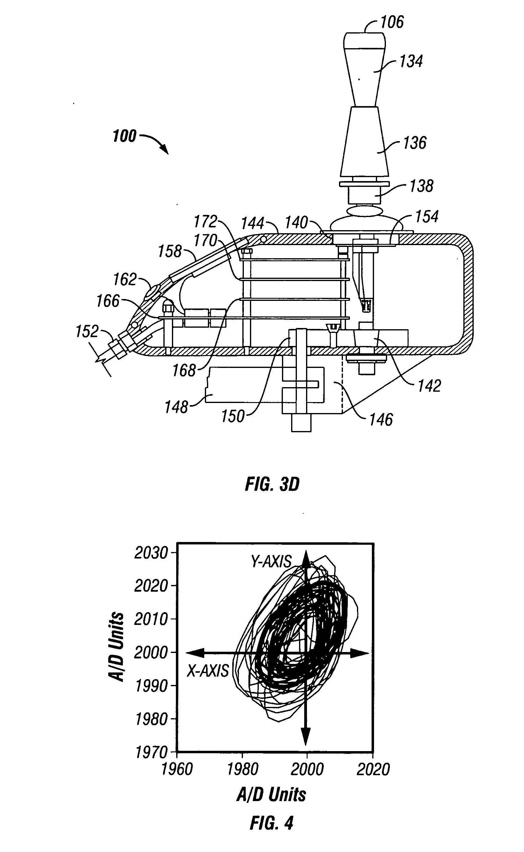
[0025] As discussed above for the first embodiment, the second embodiment of the joystick apparatus may likewise include a joystick having integrated control capability for operating multiple assistive devices, and the joystick may be operatively mounted on an electric powered wheelchair for allowing a user to operate multiple assistive devices. The joystick may further include compensation algorithms including an elliptical dead-zone representative of the joystick shaft at rest, the dead-zone representing a minimum range of forces which must be exceeded to produce motion of an electric powered wheelchair including the joystick mounted thereon, the dead-zone further representing a maximum range of forces which must not be exceeded to prevent movement of the wheelchair. The compensation algorithms may include a determination of an optimal bias axes gain for movement of the joystick shaft in left, right, forward and backward directions. The compensation algorithms may also include at least one software template for at least one of controlling bias of the joystick shaft, decreasing throw of the joystick shaft and reducing degrees of freedom of an output signal of the joystick shaft. The software template may be based upon the mathematics of super quadratics, and may be one of a square, circular, cross, elliptical and diamond shaped template. The compensation algorithms may also include filtering to reduce the effects of unwanted motions of the joystick shaft. The upper joystick segment may be detachable from the lower joystick segment for facilitating replacement of the lower joystick segment.

Problems solved by technology

It has been shown that such joysticks are inadequate for as many as 40% of potential wheelchair users, partly because they are built on a “one size fits all” philosophy.
Frequently, none of the commercial position sensing joystick controls are suitable and the user is often downgraded to single switch head arrays rather than a proportional control system.
While single switch technology can be operated with limited and imprecise limb movement, the result is generally a slow and awkward wheelchair control system.
Even in light of the aforementioned improvements in controllers, commercial controllers and position sensing joysticks are generally unable to recognize or in any way correct for an operator's unintentional hand movements.
Another major disadvantage of currently available controllers is that they only serve the electric powered wheelchair, and do not support the control of any other associated device, such as personal computers or environmental control systems.
While such joysticks are known in the industry, these joysticks have had limited application in the field of electric powered wheelchairs due to the associated limitations in the ability of user to adequately operate the joystick.
Moreover, the damped control methodology has primarily been used for position sensing, and not for control of electric powered wheelchairs.
Lastly, with regard to wheelchair driving simulators, while simulators have indeed found applications in the automotive field, as with automobile driving simulators, for example, such simulators are however not applicable to wheelchair driving.
Moreover, no known driving simulators have been used to tune electric powered wheelchairs or associated joysticks.

Method used


Image

  • Variable compliance joystick with compensation algorithms
  • Variable compliance joystick with compensation algorithms
  • Variable compliance joystick with compensation algorithms

Examples


first embodiment

[0049] variable compliance joystick 100 will now be described in detail.

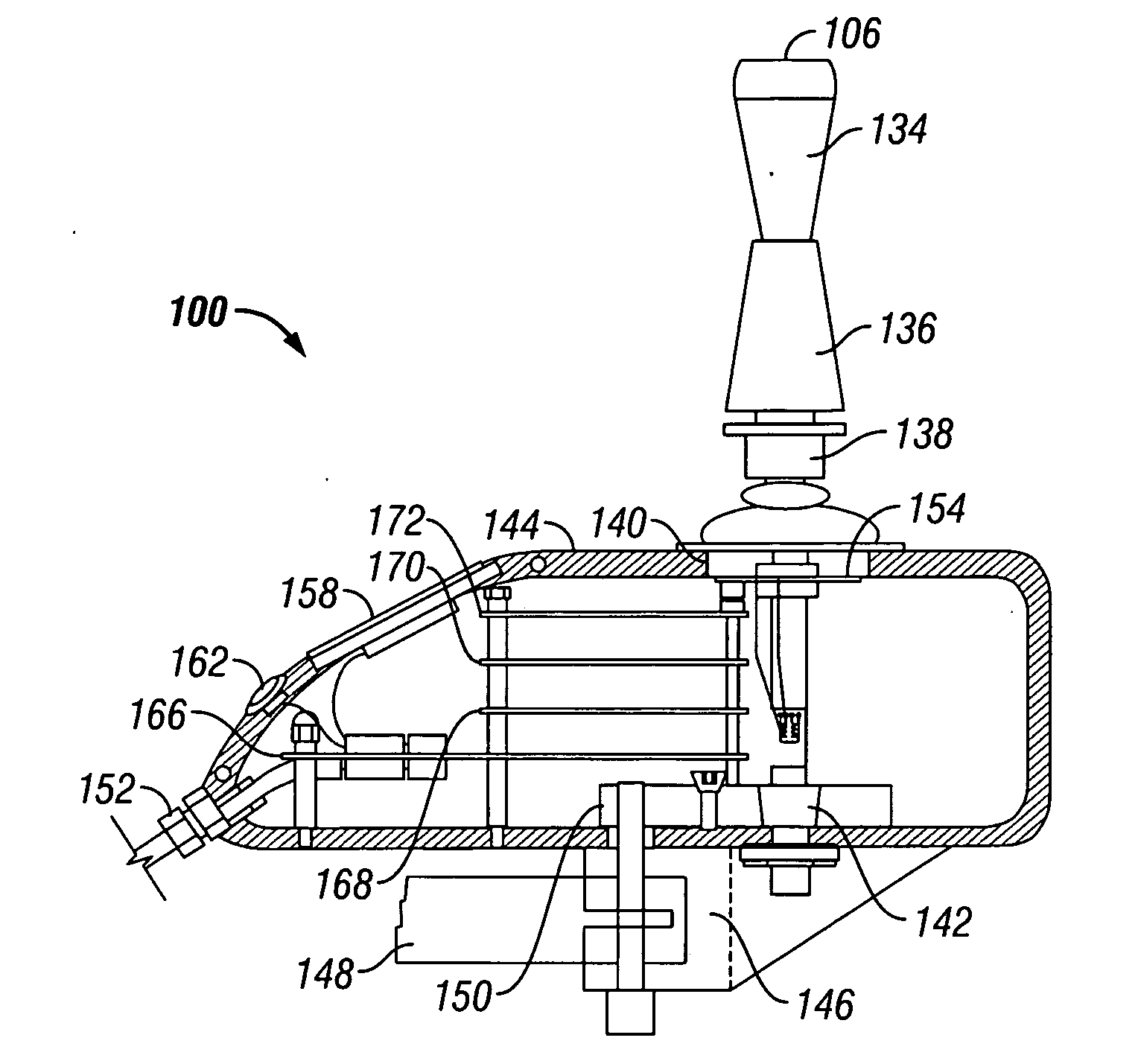
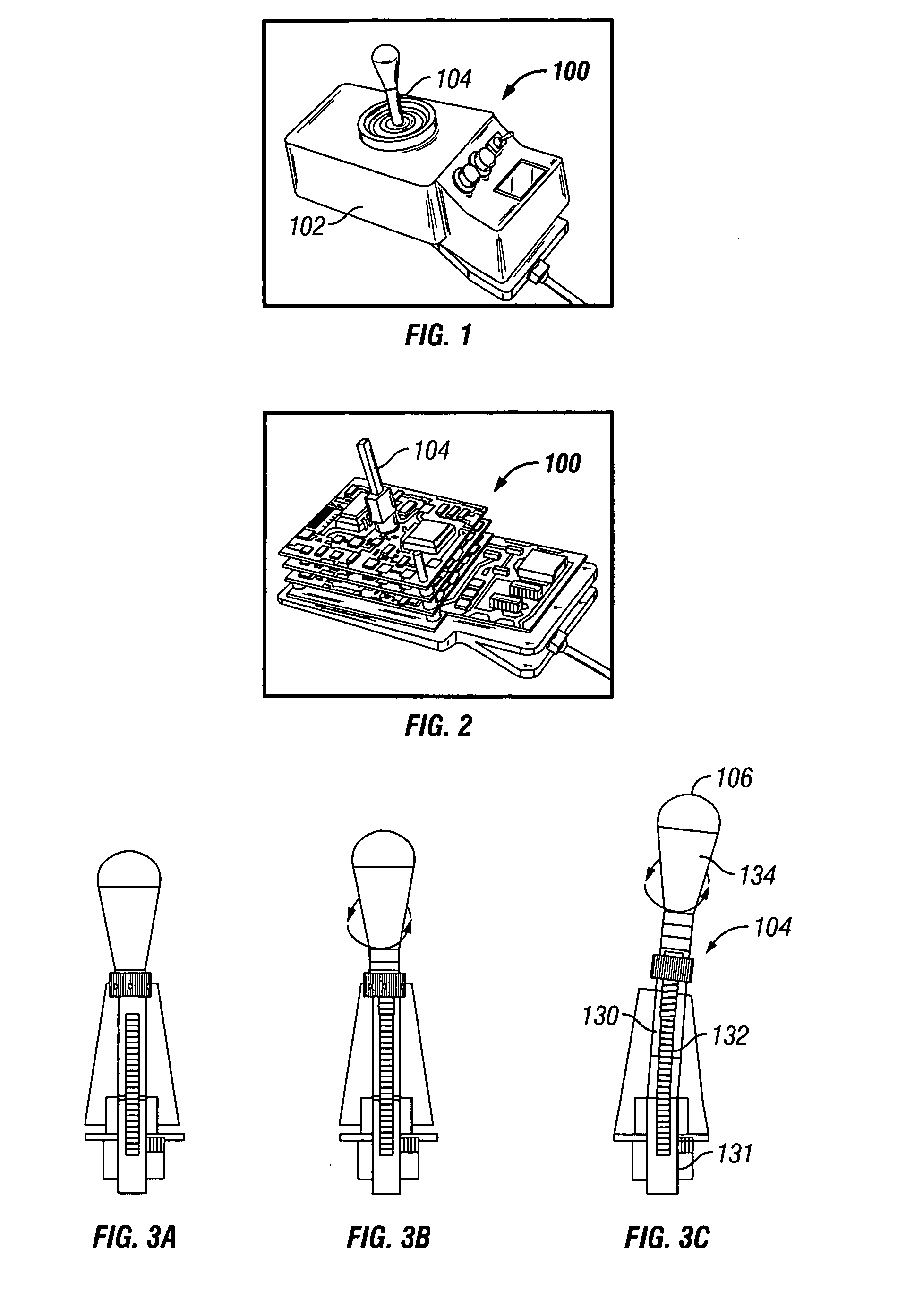
[0050] Specifically, as illustrated in FIGS. 1-14, the present invention provides a variable compliance joystick 100 with mechanical and software customization, and with an integrated control capability, and a method of systematically determining the best mechanical settings and compensatory algorithms to embed in joystick 100 to offer an individual with substantial upper extremity motor impairments a personal fit and maximum function. Generally, variable compliance joystick 100 may be used for driving Electric Powered Wheelchairs, for controlling additional rehabilitation technology, and for other related operations as discussed in detail below.

[0051] The aforementioned features of variable compliance joystick 100 and the method of systematically determining the best mechanical settings and compensatory algorithms to embed in joystick 100 will first be broadly described.

[0052] With regard to mechanical custom...

second embodiment

[0115] variable compliance joystick 200 will now be described in detail with reference to FIGS. 15-18. It should be noted that the features and methods discussed above with reference to FIGS. 4-14 for joystick 100 are likewise applicable to joystick 200, as would be readily apparent to those skilled in the art.

[0116] Turning now to FIGS. 15-18, joystick 200 may include a housing (not shown) similar to housing 102, and shaft 204 having a handle 206 at an upper end thereof. An open center gimbal 208 may be provided for further stabilizing the bending of flexible extension 250 (similar to flexible extension 136 of the first embodiment). Gimbal 208 may include hollow gimbal ring 210, including pivotally mounted yoke legs 212 at pivot pins 276; the yoke legs being further affixed to circular yoke column 214. As shown in FIG. 18, yoke legs 212 may be disposed in suitable apertures 274 in ring 210. Gimbal ring 210 may be further pivotally mounted on bushings 272 whose journals 270 may be p...


PUM


Abstract

The present invention provides variable compliance joysticks with mechanical and software customization, and with an integrated control capability, and a method of systematically determining the best mechanical settings and compensatory algorithms to embed in the joysticks to offer an individual with substantial upper extremity motor impairments a personal fit and maximum function. The joysticks may include components for varying the compliance and dampening of the joystick shaft. The method may include providing the user access to operate the joysticks, operatively connecting the joysticks to a driving simulator, displaying an icon on the driving simulator, controlling movement of the icon by the joysticks, evaluating performance of the user based upon the user's ability to control movement of the icon, and modifying hardware settings and software algorithms for the joysticks based upon the evaluation.

Description

RELATED APPLICATIONS [0001] This application claims benefit of priority of Provisional Application Ser. No. 60 / 406,682, filed Aug. 29, 2002, and is a continuation-in-part of PCT App. Serial No. PCT / US03 / 27163, filed Aug. 29, 2003.BACKGROUND OF INVENTION [0002] a. Field of Invention [0003] The invention relates generally to electric powered wheelchairs, and, more particularly to an apparatus and method for customized control of an electric powered wheelchair. [0004] b. Description of Related Art [0005] Position sensing devices are integral components of computing systems, the ubiquitous “mouse” being one of the best examples. Joysticks are also common, and find applications in computer games, medical devices, wheelchairs, robotics, aircraft, advanced vehicles, and other devices. Other examples of position sensing devices include trackballs and virtual reality equipment such as helmets, goggles, gloves, and foot pedals. The earliest joysticks were basically a simple arrangement of con...

Claims


Application Information

Patent Timeline
Patent Type & Authority Applications(United States)
IPC IPC(8): G05G9/047G06F3/038G09G5/08
CPCA61G2203/14A63F2300/1018G05G9/047G05G2009/04725Y10T74/20201G05G2009/04762G06F3/0338G06F3/038G05G2009/04729
Inventor COOPER, RORY A.SPAETH, DONALDGUO, SONGFENG
Owner COOPER RORY A
Learn More