
Threshold matrix, a method of generating the same, and a method of assigning the same

Inactive Publication Date: 2005-09-08
FUJIFILM HLDG CORP +1
View PDF35 Cites 15 Cited by
  • Summary
  • Abstract
  • Description
  • Claims
  • Application Information

AI Technical Summary

Benefits of technology

[0024] It is an object of the present invention to provide a threshold matrix and a method of generating such a threshold matrix which will solve the problems of the conventional FM screens. The generated threshold matrix is optimum for use in an output system, and is capable of reproducing high-quality images of excellent printability.
[0025] Another object of the present invention is to provide a method of assigning a threshold matrix which is capable of generating threshold matrixes for five or more color separations for reproducing a color image with a light workload, and which is capable of generating threshold matrixes that do not cause shortcomings in superimposing images.

Problems solved by technology

FM screens also cause disadvantages in that a dot gain tends to become large and images are reproduced unstably when images are printed, or when films are output in an intermediate printing process, or when a printing plate is output by a CTP apparatus.
For example, if a dot size is determined to be a 3×3-pixel FM screen dot size with respect to an output system which is incapable of stably reproducing 2×2-pixel FM screen dots for highlight areas, then the resolution (referred to as pattern frequency or pattern resolution) for intermediate tones is lowered, resulting in a reduction in the quality of images.
However, when one plate is not completely superimposed on another plate with some displacement, less superimposition of dots causes unstable color reproduction and unevenness or irregularity of hue or shade in the image.
However, it is quite difficult to generate threshold matrixes each having a different threshold array, and it requires a heavy workload.
Further, it is difficult to handle five or more thresholds for color plates in a RIP system etc. generally using four threshold matrixes for four C, M, Y and K colors.

Method used


Image

  • Threshold matrix, a method of generating the same, and a method of assigning the same
  • Threshold matrix, a method of generating the same, and a method of assigning the same
  • Threshold matrix, a method of generating the same, and a method of assigning the same

Examples


Embodiment Construction

[0097] In the description, a method of generating a threshold matrix is described first, and then a method of assigning a threshold matrix is described.

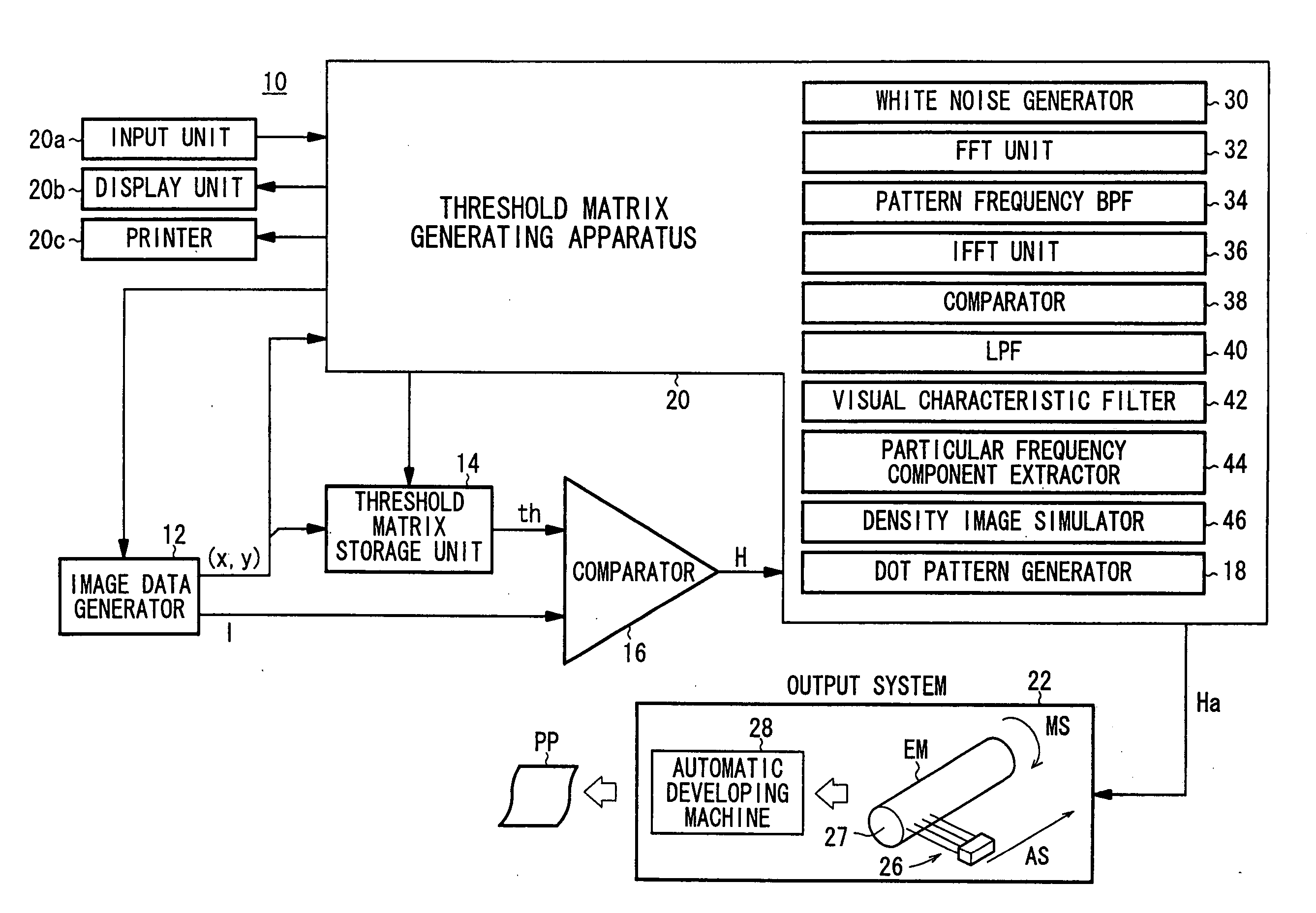
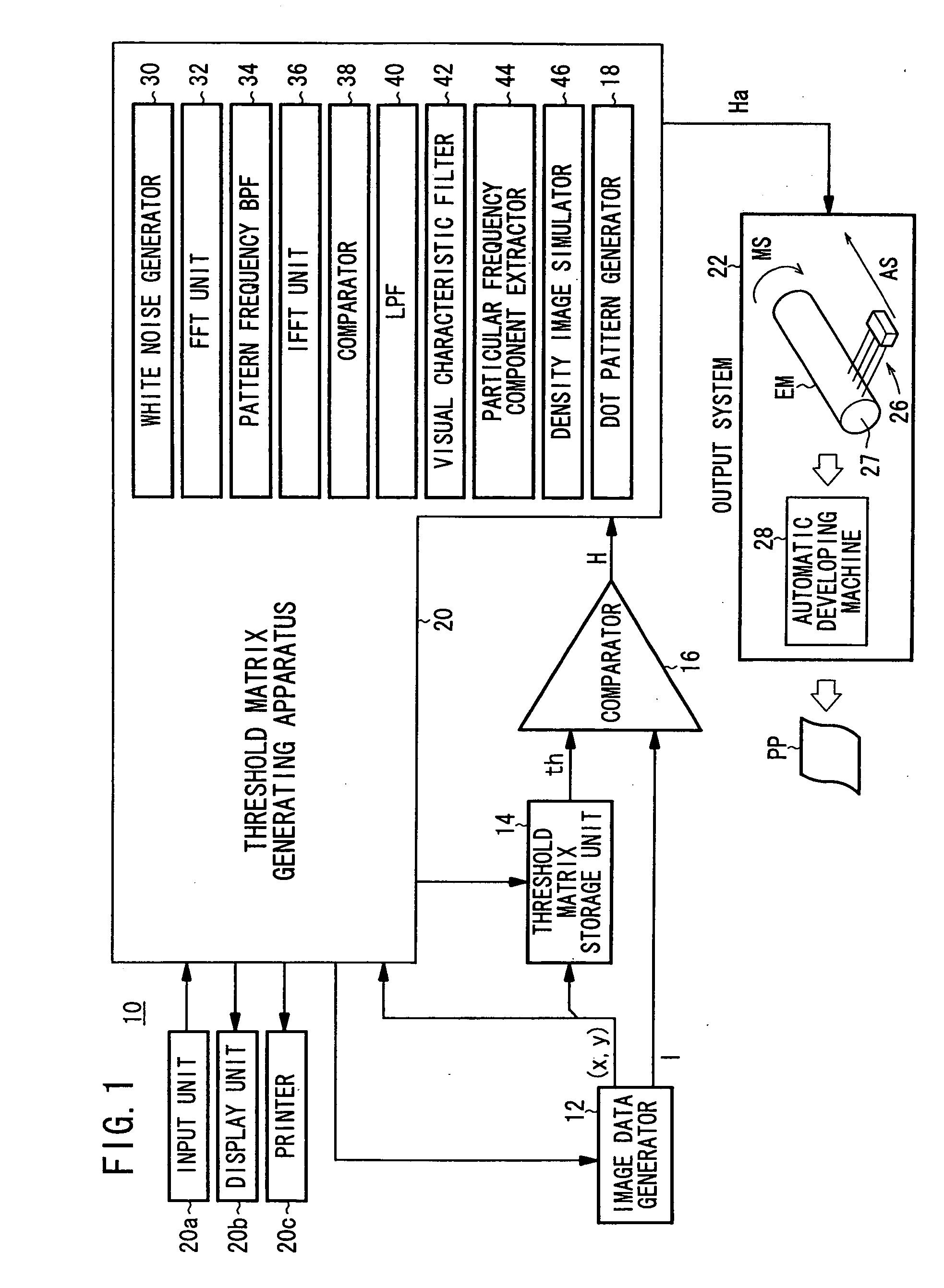
[0098]FIG. 1 shows a basic arrangement of a threshold matrix generating system 10 according to an embodiment of the present invention.

[0099] As shown in FIG. 1, the threshold matrix generating system 10 has an image data generator 12 for generating continuous-tone image data I including a test pattern of uniform density with a tone value u (for example, u=256) and also generating a two-dimensional address (x, y) of the image data I, a threshold matrix storage unit 14 for storing a plurality of threshold matrixes TM (or TMX, TX) and outputting a threshold th read by the address (x, y), a comparator 16 for comparing the threshold th and the image data I and outputting binary image data H representative of a dot pattern in which no predetermined screen ruling or screen angle is defined, a threshold matrix generating apparatus 20 inclu...


PUM


Abstract

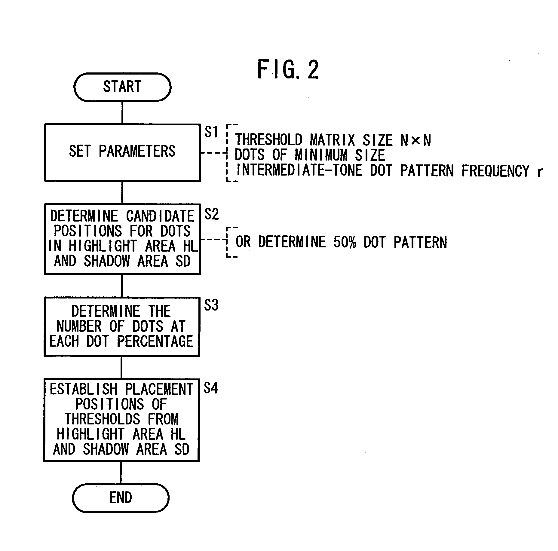
The number of pixels of a dot of a minimum size, a pattern frequency of an intermediate tone, the number of new dots of the minimum size at each dot percentage are determined. Then, thresholds in the threshold matrix are determined so that the optimum dot pattern at each dot percentage is obtained, and a threshold matrix is generated. A threshold matrix for C-separation is assigned to a separation for R that is complementary to C. A threshold matrix for M-separation is assigned to a separation for G that is complementary to M. A threshold matrix for Y-separation is assigned to a separation for B that is complementary to Y.

Description

BACKGROUND OF THE INVENTION [0001] 1. Field of the Invention [0002] The present invention relates to a threshold matrix and a method of generating such a threshold matrix, for generating a screen which is called an FM screen or a stochastic screen for converting a continuous-tone image input with a tone value u (for example, u=256) into a dot pattern representative of a v-valued (2≦v<u) image in which no screen ruling or screen angle is defined. More particularly, the present invention relates to a threshold matrix, a method of generating such a threshold matrix and a method of assigning such a threshold matrix that are suitable for use in a printing-related apparatus (output system) such as a filmsetter, a platesetter, a CTP (Computer To Plate) apparatus, a CTC (Computer To Cylinder) apparatus, a DDCP (Direct Digital Color Proof) system, etc., an ink jet printer, or an electrophotographic printer. [0003] In the present invention, the dot pattern in which no screen ruling or scre...

Claims


Application Information

Patent Timeline
IPC IPC(8): G06T1/00G06T5/00H04N1/405H04N1/52H04N1/60B41J2/52
CPCH04N1/52H04N1/4051
Inventor INOUE, YOSHIAKI
Owner FUJIFILM HLDG CORP
Learn More