Waveguide-type optical splitter and waveguide-type optical module having the same

a technology of optical splitter and optical module, which is applied in the field of waveguide-type optical splitter and waveguide-type optical module, can solve the problems of not meeting the needs of customers, pdl cumulative increase, and adverse influence on optical characteristics

Inactive Publication Date: 2005-09-08
NEC CORP
View PDF10 Cites 29 Cited by
  • Summary
  • Abstract
  • Description
  • Claims
  • Application Information

AI Technical Summary

Benefits of technology

[0022] As described above, according to this invention, the spot size in the input end of the slab waveguide is enlarged and the angle of diffraction of the optical signal inside the slab waveguide is to be small thereby enabling the angle of diffraction to be uniform regardless of a wavelength of the optical signal. Because of this, as the wavelength of the optical signal is longer, the angle of diffraction can be small by enlarging the spot size, and thus the wavelength dependence of loss uniformity between the waveguides for output can be improved very much.

Problems solved by technology

In the PLC type optical splitter, while it has characteristics as compact and high reliability, double refraction is generated due to the difference in a linear expansion coefficient between a Si substrate and SiO2 thereby causing an adverse influence on optical characteristics.
However, when the Y-branched structure of the multi-stage is applied to the PLC type optical splitter 80 in which the double refraction is large, the PDL cumulatively increases according to the number of the branch, therefore it may not meet the needs from customers.
However, in the conventional star couplers, despite optical power is large in a waveguide for output at the center, it becomes small in a waveguide for output at the end.
Accordingly, the conventional star couplers have weakness in that loss uniformity in each port after being branched off is inferior to the one in the Y-branched type while the favorable polarization dependence can be obtained in the waveguide where the double refraction is large.

Method used


Image

  • Waveguide-type optical splitter and waveguide-type optical module having the same
  • Waveguide-type optical splitter and waveguide-type optical module having the same
  • Waveguide-type optical splitter and waveguide-type optical module having the same

Examples


first embodiment

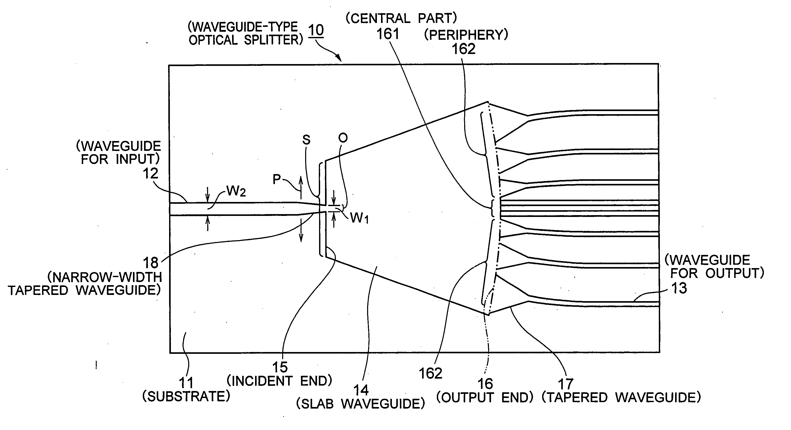
[0031]FIG. 3 is a plan view which shows a waveguide-type optical splitter according to the present invention. FIG. 4 is a partial enlarged view of the FIG. 3. Descriptions are provided below with reference to the FIG. 3 and the FIG. 4.

[0032] In a waveguide-type optical splitter 10 of this embodiment, a waveguide for input 12, a plurality of waveguides for output 13 and a slab waveguide 14 are formed on a substrate 11. The waveguide for input 12 is so configured as to introduce an optical signal. The slab waveguide 14 is so configured as to cause the optical signal introduced in the waveguide for input 12 to branch off by diffraction and to propagate. The plurality of waveguides for output 13 are so configured as to output individually a plurality of optical signals which have been branched off inside the slab waveguide 14. The slab waveguide 14 has an incident end 15 and an output end 16. In the slab waveguide 14, the output end 16 is formed in a shape of an arc in the incident end ...

fourth embodiment

[0051]FIG. 7 is a plan view showing the waveguide-type optical splitter according to the present invention. Descriptions are provided below with reference to this drawing. However, regarding the same part as in the FIG. 3, explanations are omitted by denoting the same reference numeral.

[0052] The waveguides for output 13 shown in the FIG. 7 is provided with a function for reducing the transmission loss of the optical signal. In a joining point of the waveguide for output 13 and the tapered waveguide 17 which is a part of the waveguide for output 13 (hereinafter these waveguides are referred as a waveguide for output 13) and the slab waveguide 14, loss in power (hereinafter referred as “insertion loss”) due to a scattering of light is generated. At this time, if a plurality of waveguides are crossed over a plurality of waveguides for output, the loss at the output end is reduced.

[0053] Consequently, the waveguides for output 13 shown in the FIG. 7 is arranged a plurality of waveguid...


PUM


Abstract

To solve the wavelength dependence of loss uniformity between waveguides for output. A waveguide for input for introducing an optical signal, a slab waveguide for branching off the optical signal introduced in the waveguide for input by diffraction and propagating, and a plurality of waveguides for output for outputting individually a plurality of optical signals which are branched off inside of the slab waveguide are provided. The waveguide for input is configured such that an output end thereof is connected to an incident end of the slab waveguide and has a function for converting a spot size of the optical signal on the incident end of the slab waveguide at a connection point with the slab waveguide.

Description

BACKGROUND OF THE INVENTION [0001] 1. Field of the Invention [0002] The present invention relates to a waveguide-type optical splitter and a waveguide-type optical module having the same which are used in such as a PON (Passive Optical Network) system in order to branch off light into plural. [0003] 2. Description of the Related Art [0004] Applications to subscribers of the PON system have been active for establishing optical communication systems at low cost. The PON system indicates the efficient use to be possible by branching off an optical fiber with an optical splitter in access sections, thus remarkable cost reduction is realized. [0005] In this PON system, an optical splitter module is used in branching off of light. As this optical splitter module, required are a low insertion loss, low polarization dependence and high reliability. A PLC (Planar Lightwave Circuit) type optical splitter satisfies these needs and has been produced several tens of thousands per month only in J...

Claims


Application Information

Patent Timeline
Patent Type & Authority Applications(United States)
IPC IPC(8): G02B6/122G02B6/26
CPCG02B6/1228G02B6/2808G02B6/125
Inventor YAMAZAKI, HIROYUKIHATANAKA, TAKAAKI
Owner NEC CORP
Why Eureka
Try Eureka