Focused ion beam low kV enhancement

a technology of focused ion beams and charged particles, applied in the direction of heat measurement, particle separator tube details, instruments, etc., can solve the problems of affecting the broader application of broader resolution, damage to workpieces, and poor spot size performance needed to make thin lamellas

Active Publication Date: 2015-01-13
FEI CO
View PDF4 Cites 4 Cited by
  • Summary
  • Abstract
  • Description
  • Claims
  • Application Information

AI Technical Summary

Benefits of technology

[0014]An object of the invention is to provide a method and apparatus for forming a focused ion beam spot size that is substantially improved from conventional spot sizes using low kV.
[0015]This invention consists of biasing the middle section of the FIB column to a high negative voltage allowing the beam to move at higher potential than the final beam energy inside that section of the column, which helps reduce aberrations and coulomb interactions. The result is significant improvement in spot size at the low kV.

Problems solved by technology

Despite their widespread use, existing ion sources possess limitations that impede progress toward broader applications and higher resolution.
The use of focused ion beams with high landing energies at the target, which is above 5 keV, can cause significant damage to the work piece.
However, the use of beams with low landing energy results in poor spot size performances needed to make thin lamellas.
But the performance improvements in using low C objective lenses and tetrode / pentode switchable lenses is very small and not sufficient for imaging and creating ultrathin lenses.
Furthermore, it is difficult to accelerate ions from a source without inducing a large energy spread in the resultant beam.
The larger the spatial extent of the ion source, the more difficult it is to focus the ions to a point.
Placing the deflector below the objective lens, however, increases the working distance, thereby increasing the beam aberration.
With the deflector above the lens, however, when the beam is deflected, it is moved away from the center of the lens, thereby increasing certain aberrations.

Method used


Image

  • Focused ion beam low kV enhancement
  • Focused ion beam low kV enhancement
  • Focused ion beam low kV enhancement

Examples


Embodiment Construction

[0022]The invention produces significant improvements in spot sizes produced by a focused ion beam by biasing the middle section of focused ion beam column to high negative voltages, and is particularly useful when in making ultrathin lamellas.

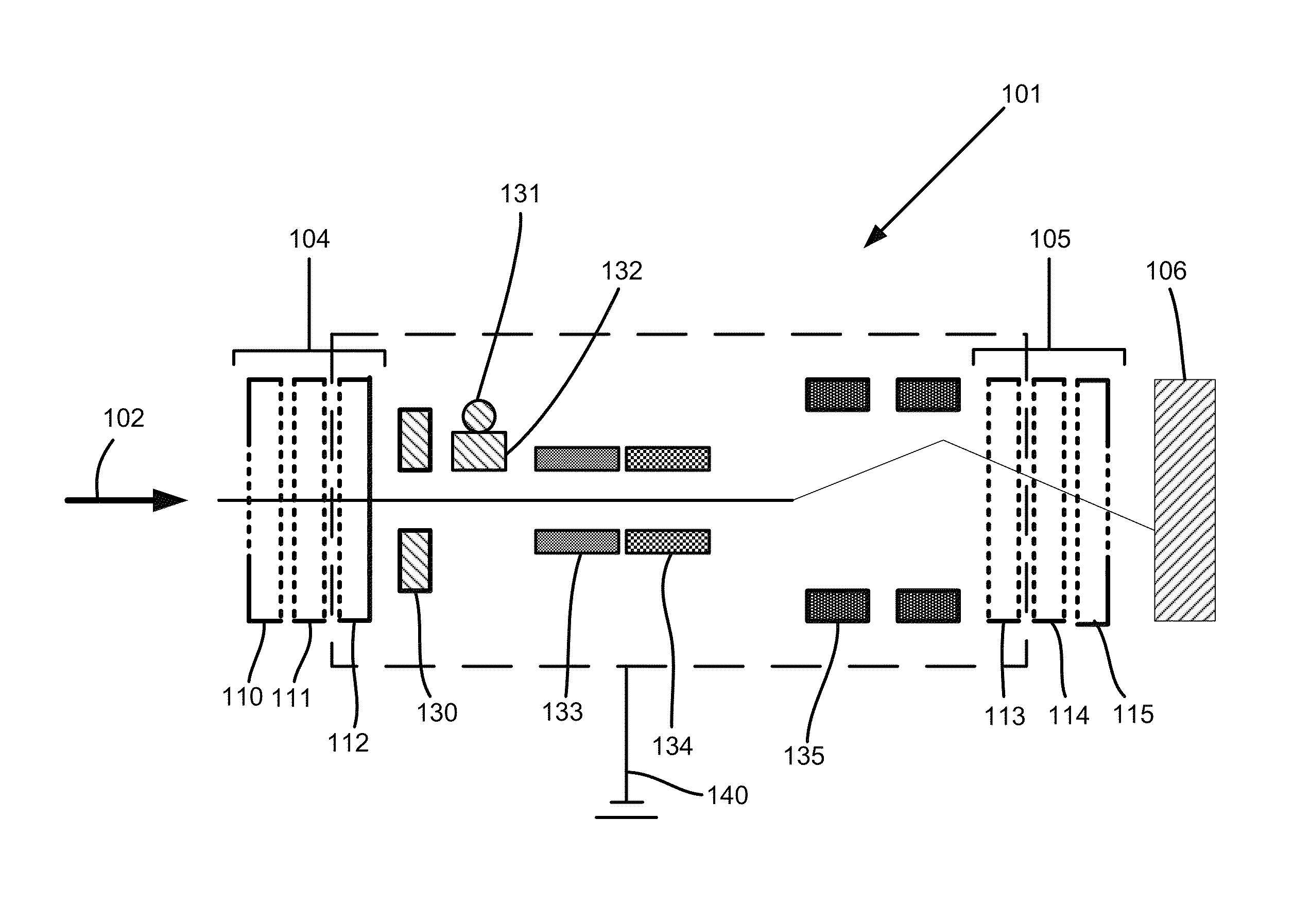
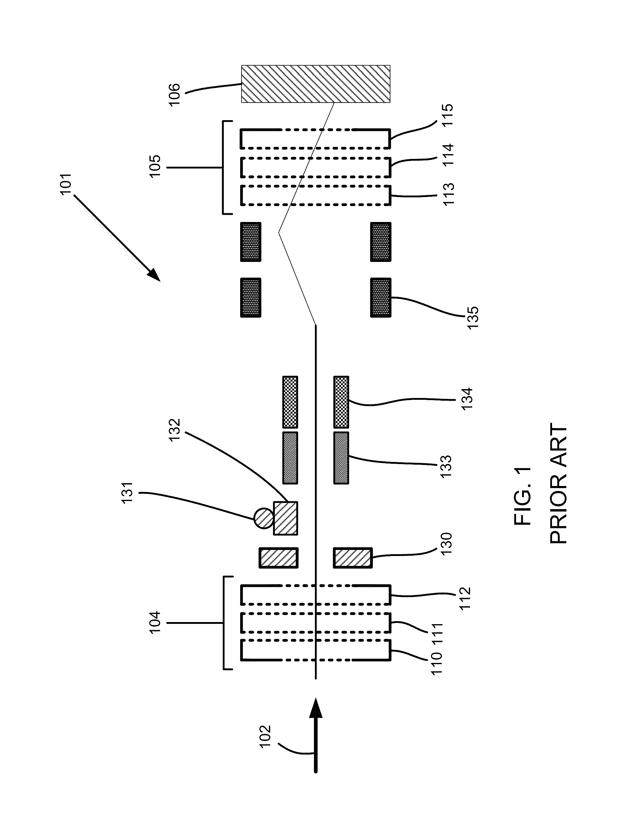
[0023]FIG. 2 shows a focused ion beam column 101 having a source of electrons102 in accordance with embodiments of the current invention. The source of electrons 102 has an optical axis that traverses the length of the focused ion beam column 101 and is directed to a target 106. The focused ion beam column 101 is comprised of two lens systems 104, 105. Lens system 104 is composed of three electrodes 110, 111, and 112. Lens system 105 is composed of three electrodes 113, 114, and 115.

[0024]In accordance with embodiments of the current invention, the middle section of the focused ion beam column 101 is composed of a booster tube 120. The booster tube may be composed of a tube that encapsulates the middle components of the focused ion beam column...


PUM


Abstract

The invention provides a charged particle beam system wherein the middle section of the focused ion beam column is biased to a high negative voltage allowing the beam to move at higher potential than the final beam energy inside that section of the column. At low kV potential, the aberrations and coulomb interactions are reduced, which results in significant improvements in spot size.

Description

TECHNICAL FIELD OF THE INVENTION[0001]The present invention relates to charged particle beam systems, such as a focused ion beam system.BACKGROUND OF THE INVENTION[0002]Focused ion beam systems direct charged particles onto a work piece, or target, for processing the work piece or for forming an image of the work piece. Charged particle beam systems are used, for example, in integrated circuit fabrication and other nanotechnology processing. Charged particles beam systems typically include a source of particles, a beam blanker, accelerating lenses, focusing optics, and deflection optics.[0003]High resolution focused ion beams (FIBs) have proven useful for a variety of tasks such as microscopy, lithography, micromachining (ion milling and material deposition), and dopant implantation. Over the years, a number of ion sources have been developed for focused ion beam applications, including gas-phase field ionization, plasma, and liquid metals. Of all the sources developed to date, the ...

Claims


Application Information

Patent Timeline
Patent Type & Authority Patents(United States)
IPC IPC(8): H01J37/05H01J49/26H01J49/10G01R31/305H01J3/02H01J37/04
CPCH01J37/04H01J37/3056H01J3/026H01J2237/04735H01J2237/1518H01J2237/1534H01J2237/28H01J2237/31749H01J2237/04756H01J37/07H01J37/21H01J37/10H01J37/06H01J37/1477H01J37/248H01J2237/0473
Inventor MAAZOUZ, MOSTAFA
Owner FEI CO
Why Eureka
Try Eureka