Engine system and method with cylinder deactivation
- Summary
- Abstract
- Description
- Claims
- Application Information
AI Technical Summary
Benefits of technology
Problems solved by technology
Method used
Image
Examples
Embodiment Construction
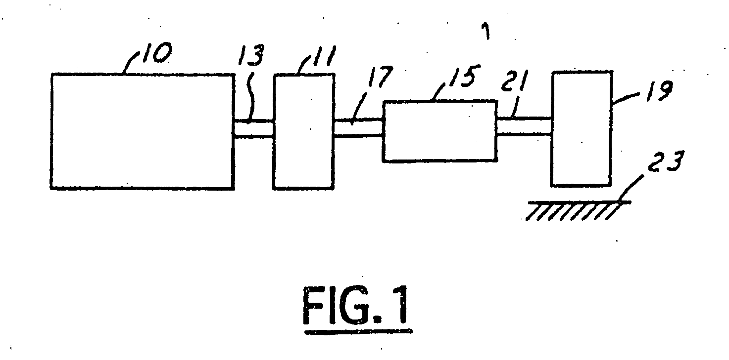
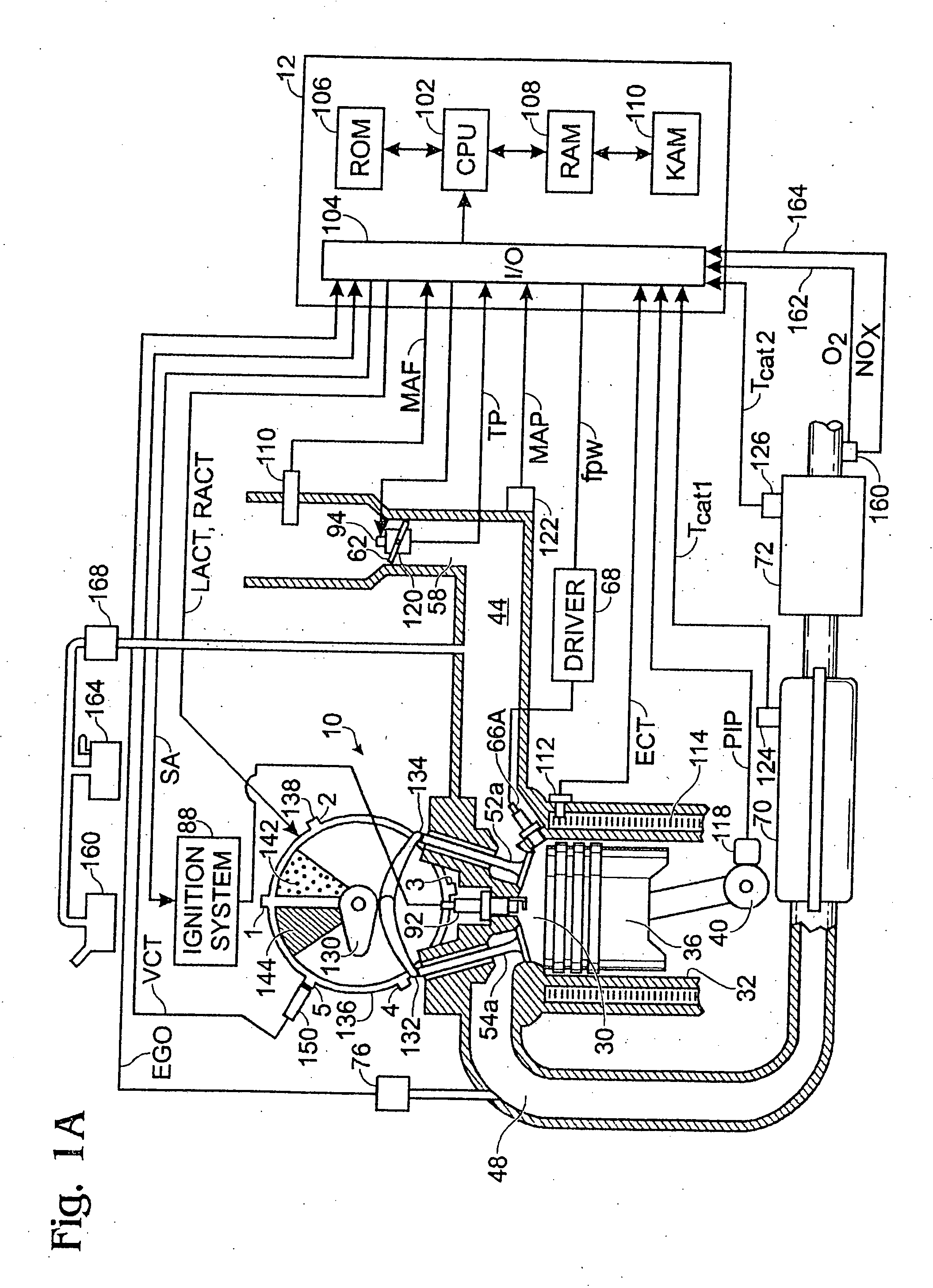
[0017] Referring to FIG. 1, internal combustion engine 10, further described herein with particular reference to FIGS. 1A and 1B, is shown coupled to torque converter 11 via crankshaft 13. Torque converter 11 is also coupled to transmission 15 via turbine shaft 17. Torque converter 11 has a bypass, or lock-up clutch 14 which can be engaged, disengaged, or partially engaged. When the clutch is either disengaged or partially engaged, the torque converter is said to be in an unlocked state. The lock-up clutch 14 can be actuated electrically, hydraulically, or electro-hydraulically, for example. The lock-up clutch 14 receives a control signal (not shown) from the controller, described in more detail below. The control signal may be a pulse width modulated signal to engage, partially engage, and disengage, the clutch based on engine, vehicle, and / or transmission operating conditions. Turbine shaft 17 is also known as transmission input shaft. Transmission 15 comprises an electronically c...
PUM
 Abstract
Description
Claims
Application Information
 - R&D
- Intellectual Property
- Life Sciences
- Materials
- Tech Scout
- Unparalleled Data Quality
- Higher Quality Content
- 60% Fewer Hallucinations
Browse by: Latest US Patents, China's latest patents, Technical Efficacy Thesaurus, Application Domain, Technology Topic, Popular Technical Reports.
© 2025 PatSnap. All rights reserved.Legal|Privacy policy|Modern Slavery Act Transparency Statement|Sitemap|About US| Contact US: help@patsnap.com


